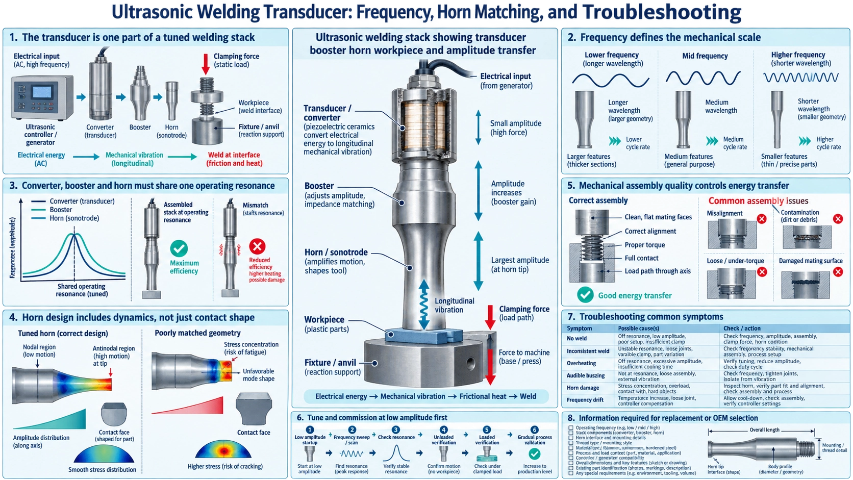
The transducer is one part of a tuned welding stack
An ultrasonic welding transducer converts generator voltage into high-frequency mechanical vibration. It is normally connected to a booster and horn, which transmit and transform amplitude into the workpiece. The converter, booster, horn, interfaces, generator and fixture operate as one tuned system.
Replacing a converter by frequency and power label alone is risky. Resonance, impedance, capacitance, bolt pattern, interface diameter, preload, amplitude rating and mass loading must fit the existing stack. The process material, joint design, clamp force and weld control also determine the result.
Frequency defines the mechanical scale
Lower-frequency systems such as 20 kHz commonly support larger horns, higher displacement and high-power industrial welding. Higher frequencies can use smaller acoustic components and may suit small or delicate assemblies. Frequency selection changes the wavelength and therefore the physical dimensions of every resonant component.
The BBWD-20KP2000 20 kHz 2000 W welding transducer is intended as a converter-level component. Its rating does not establish the allowable horn geometry, weld force or cycle rate of a finished machine.
Converter, booster and horn must share one operating resonance
The converter creates vibration, the booster adjusts amplitude and provides a clamping node, and the horn delivers motion to the joint. Each component must be designed for the operating frequency and installed with clean, flat interfaces and correct preload. A small frequency mismatch can increase electrical current, heat and stress.
Booster gain and horn gain multiply the converter amplitude. More gain is not automatically better: excessive tip amplitude can crack the horn, damage the transducer, mark the part or overload the generator. Select amplitude from material, joint and process testing.
Horn design includes dynamics, not just contact shape
The horn must resonate in the intended longitudinal mode while providing the required contact face. Length, cross-section transitions, slots, material, attachment thread and tooling details affect frequency and stress. Large or complex horns may need finite-element analysis and frequency verification after machining.
A horn tuned by itself can shift after adding replaceable tips, coatings or fixtures. The assembled stack should be scanned before production. Avoid operating near unwanted bending or torsional modes.
Mechanical assembly quality controls energy transfer
Clean all acoustic interfaces and remove burrs or raised damage. Apply the specified stud and torque procedure. Incorrect torque, damaged threads, trapped contamination or nonparallel faces create interface heating and unstable resonance.
Clamp the stack at the designed nodal flange. Clamping an antinode or constraining the horn changes resonance and can cause rapid failure. Support cables and cooling lines without imposing side load on the converter.
Tune and commission at low amplitude first
Use the generator’s frequency scan or an impedance analyzer to identify resonance, antiresonance and competing modes. Assemble the intended stack before final judgment. Start at low amplitude and observe frequency tracking, current, phase, temperature and abnormal sound.
Run representative parts while increasing amplitude, force and weld time within controlled limits. Establish acceptance windows for energy, peak power, collapse distance, time or force according to the machine’s control method. Save a healthy baseline for later comparison.
Troubleshooting common symptoms
- Generator overloads at start: inspect resonance mismatch, cracked horn, loose interface, wiring and excessive mass.
- Converter or joint heats rapidly: check torque, damaged faces, off-frequency operation, cooling and duty cycle.
- Amplitude is low: verify generator output, booster ratio, horn tuning, preload and mechanical constraints.
- Weld strength varies: inspect part fit, joint geometry, fixture support, trigger force, amplitude and material consistency.
- Horn cracks repeatedly: review stress concentration, gain, unwanted modes, surface damage and actual cycle load.
Do not keep increasing amplitude to hide a mechanical or joint-design problem. That can transfer the failure to a more expensive component.
Information required for replacement or OEM selection
Provide frequency, generator model and voltage, target power, converter capacitance and impedance data, mechanical interface drawing, booster and horn mass, mounting method, target amplitude, duty cycle, cooling, material, joint design and acceptance criteria. For replacement, include frequency scans of both the healthy reference and failed stack when available.
The TWI overview of ultrasonic welding explains the process mechanism and the roles of the sonotrode, pressure and vibration. For stack development, coordinate the generator and converter with the circuit-matching guide, preserve healthy reference data with the transducer testing guide, and use the replacement guide before fitting a nominally similar converter.
FAQ
Can any 20 kHz transducer work with any 20 kHz horn?
No. The complete stack must match mechanically and electrically, including interfaces, resonance, amplitude, load and generator behavior.
What does the booster do?
It changes amplitude according to its gain ratio and normally provides the nodal mounting location between converter and horn.
Why does the generator lose frequency lock?
Possible causes include a cracked or loose stack, excessive heating, an unsuitable horn, competing vibration modes, changing load or electrical connection problems.
Should the stack be tested without parts?
A low-amplitude scan is useful, but production validation must include the real fixture, parts, force and cycle because the operating load changes system behavior.