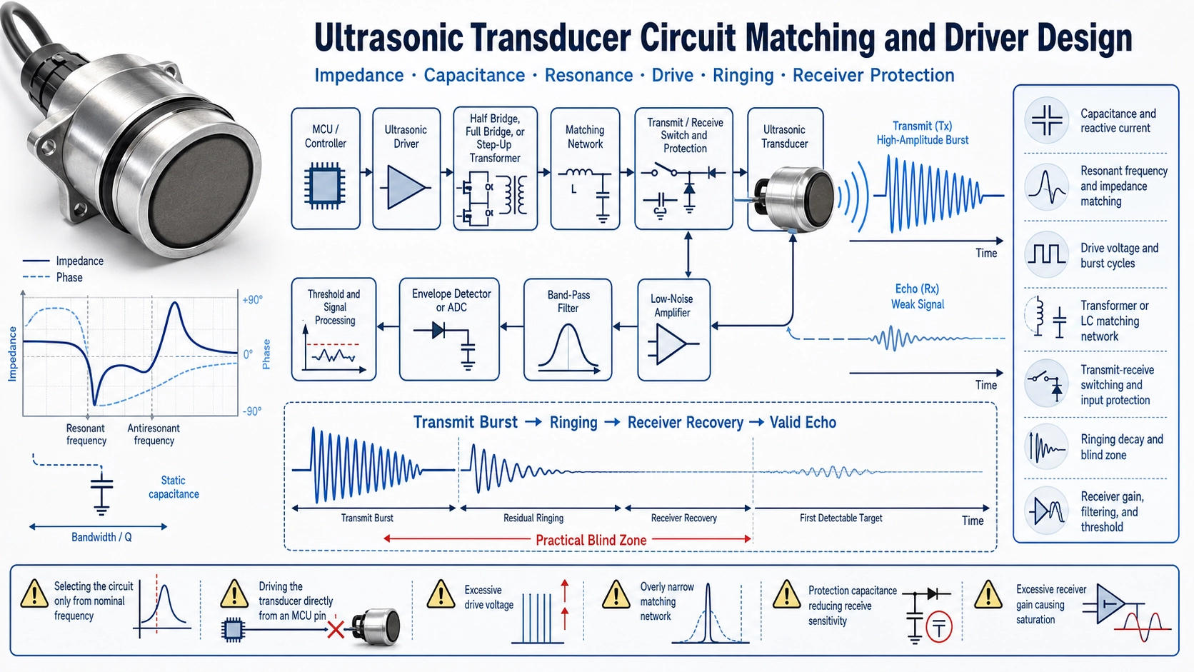
An ultrasonic transducer is part of an electrical and acoustic system
A transducer with the correct nominal frequency is not automatically compatible with an existing circuit. Transmit strength, current demand, recovery time, receive sensitivity, blind zone, noise immunity, and long-term reliability depend on the interaction between the piezoelectric element, housing, cable, driver, matching network, transmit-receive switch, protection, analog front end, and signal-processing settings.
This article focuses on circuit-level integration. For the broader information needed in a custom inquiry, see our custom ultrasonic transducer specification guide.
Start with measured electrical data, not only a frequency label
Request or measure the impedance curve around the intended operating band. Important values include resonant and antiresonant frequencies, impedance magnitude and phase, static capacitance, dielectric loss where relevant, sensitivity, allowable drive, and the test condition. Housing, potting, cable length, mounting, temperature, and production variation can shift these values.
| Parameter | Why the circuit designer needs it |
|---|---|
| Static capacitance | Sets reactive current and influences driver, switch, and tuning requirements |
| Resonant frequency and impedance | Helps select burst frequency and estimate electrical loading |
| Bandwidth or Q | Affects ring-up, ringing, pulse length, and frequency tolerance |
| Maximum drive condition | Protects the ceramic, electrodes, bonding, and housing from overstress |
| Receive sensitivity | Influences gain, noise floor, threshold, and maximum range |
Capacitance determines reactive current
Away from resonance, a piezoelectric transducer presents a strong capacitive component. For a sinusoidal approximation, reactive current increases with frequency, capacitance, and voltage. A transducer with higher capacitance can therefore demand substantially more current from the driver even when the mechanical output requirement appears unchanged.
Driver selection should consider peak current, switching loss, source impedance, duty cycle, repetition rate, and supply droop. A low-voltage microcontroller pin is rarely an appropriate direct driver for an industrial transducer. Buffer stages, half bridges, full bridges, transformer drive, or dedicated ultrasonic drivers are commonly used depending on voltage and power.
Choose the operating frequency from the complete assembly
The nominal frequency printed on a sample is a starting point. The best transmit frequency may be near a series-resonant region, but the optimum point depends on acoustic output, bandwidth, housing resonance, receiver behavior, temperature drift, and the target application. Driving exactly at the minimum impedance can maximize electrical current without necessarily giving the best short-pulse response.
Characterize the complete transducer with its final cable and mounting. Sweep a safe frequency range and compare transmit amplitude, received echo, current, ring-up time, and ringing decay. For production, define an acceptable frequency window rather than tuning one circuit to a single golden sample.
Drive voltage, waveform, burst cycles, and duty cycle
Ultrasonic transducers may be driven by square-wave, differential, transformer-coupled, or shaped sinusoidal bursts. The relevant stress is not simply the power-supply voltage. Confirm whether the transducer limit is stated as peak, peak-to-peak, RMS, continuous sine, short burst, number of cycles, duty cycle, or another condition.
- More burst cycles can increase acoustic energy but extend ring-up and ringing.
- Higher voltage can increase output but also electrical current, dielectric stress, heating, and mechanical stress.
- Higher repetition rate raises average power even if each burst is short.
- Asymmetric drive or DC bias can create unnecessary stress and should be evaluated carefully.
Do not increase voltage to compensate for poor mechanical mounting, wrong frequency, unsuitable target geometry, or a noisy receiver.
When a transformer or matching network is useful
A transformer can step up voltage, provide topology flexibility, and transform impedance, but it also adds leakage inductance, magnetizing current, saturation limits, losses, size, and its own resonance. An inductor-capacitor matching network can reduce reactive loading or shape bandwidth, but narrow tuning may become sensitive to transducer tolerance and temperature.
Design the network from measured impedance rather than using a generic component value copied from another transducer. Verify the waveform at the actual transducer terminals with an appropriate high-voltage or differential probe. A clean driver waveform does not guarantee that the mechanical response is optimal.
Transmit-receive switching and input protection
Single-transducer pulse-echo systems must drive a relatively high transmit signal and then detect a much smaller echo on the same node. The receiver needs isolation or clamping during transmission, followed by fast recovery. Common approaches include analog switches, diode or MOSFET clamps, transformer coupling, resistor networks, and dedicated ultrasonic analog front ends.
Protection components add capacitance and leakage. If too heavy, they reduce receive sensitivity or distort the transducer. If too weak, the preamplifier can saturate or be damaged. Check maximum transient voltage, recovery time, input common-mode range, overload behavior, and the residual offset after the burst.
Ringing creates the practical blind zone
After the electrical burst stops, stored electrical and mechanical energy decays over time. This residual oscillation is ringing. During strong ringing, the receiver cannot distinguish a close target echo from the transducer’s own decay. The resulting blind zone depends on transducer Q, housing, drive cycles, voltage, matching, receiver recovery, threshold, and signal processing.
| Method | Possible benefit | Trade-off |
|---|---|---|
| Reduce burst cycles | Shorter ring-up and decay | Lower transmitted energy |
| Active damping or braking | Faster electrical decay | Additional timing and component stress |
| Broader-band transducer | Shorter pulse response | May reduce peak sensitivity |
| Separate transmitter and receiver | Receiver can recover earlier | Larger structure and acoustic crosstalk concerns |
| Higher threshold during recovery | Avoids false trigger | Can miss very close weak echoes |
Receiver gain, filtering, envelope detection, and threshold
The receiver must handle a wide dynamic range: large residual transmit energy followed by weak echoes that decrease with distance and target reflectivity. A practical chain may include low-noise gain, band-pass filtering, programmable or time-varying gain, envelope detection or direct sampling, and adaptive thresholds.
Set the filter around the actual receive spectrum, not only the nominal label. Excessively narrow filtering can distort short pulses or fail when frequency shifts. Excessive gain near the transmit event can saturate the chain. Record ambient ultrasonic noise, electrical interference, and cable pickup before finalizing thresholds.
A practical bench-matching procedure
- Measure capacitance and impedance over the expected frequency and temperature range.
- Confirm the allowable burst voltage, cycles, duty cycle, and mechanical mounting.
- Start at conservative voltage and repetition rate.
- Observe voltage and current at the transducer terminals.
- Measure ring-up, ringing decay, echo amplitude, and receiver recovery.
- Compare several transducers from different production lots.
- Test minimum and maximum target distance, weak targets, temperature, and supply tolerance.
- Lock component values only after system-level validation.
Texas Instruments application reports on PGA460 module hardware and software and ultrasonic sensing basics illustrate the interaction between transducer selection, drive topology, tuning, ringing, and receiver configuration.
Information to provide for circuit support
- Application, medium, target, range, and required blind zone
- Nominal frequency and acceptable bandwidth
- Measured capacitance and impedance curve
- Driver topology, supply voltage, and maximum terminal waveform
- Burst cycles, repetition rate, and duty cycle
- One-way or pulse-echo operation
- Cable length, shielding, connector, and grounding
- Receiver architecture, gain, filter, threshold, and sampling method
- Temperature, pressure, housing, mounting, and environmental constraints
FAQ
Can two 40 kHz transducers use the same circuit?
Not necessarily. Their capacitance, impedance, bandwidth, sensitivity, housing, cable, and ringing can differ even when both are labeled 40 kHz.
Does higher drive voltage always increase range?
It can increase transmitted energy, but range may remain limited by ringing, receiver saturation, target reflection, noise, beam pattern, or environmental attenuation.
Why does replacing the transducer change the blind zone?
The new unit may have different Q, resonance, capacitance, housing response, or cable loading, which changes ringing and receiver recovery.