Why Custom Ultrasonic Transducer Specifications Matter
A custom ultrasonic transducer quotation requires more than a frequency value, a product photo, or a short message such as “Please quote 40kHz ultrasonic transducer.” The supplier needs to understand how the transducer will be used, what medium it will work in, what acoustic performance is required, and how it will be installed in the final product.
Two ultrasonic transducers with the same nominal frequency can be completely different. For example, a 40kHz transducer may be used for distance measurement, level measurement, parking assistance, or another sensing application. However, the housing, beam angle, sensitivity, capacitance, waterproof structure, cable, and mounting method may all be different.
Complete specifications help shorten technical communication, reduce sample selection errors, and improve the chance that the first test sample will match the application. For OEM projects, clear RFQ information also helps the supplier evaluate tooling cost, sample feasibility, production process, and long-term supply stability.
Step 1: Define the Application
The application is the first and most important information for a custom ultrasonic transducer quotation. Frequency alone does not define the product. The same frequency can be used in different systems, but the acoustic design, power level, housing, and electrical matching may not be interchangeable.
Distance Measurement
For distance measurement, the transducer must be selected according to measuring range, target size, target surface, beam angle, blind zone, and installation environment. Air-based distance measurement usually requires stable transmission and echo reception over a defined range.
Typical information to provide includes the required minimum and maximum distance, target material, target size, working environment, expected beam coverage, and whether the transducer will be used as a transmitter, receiver, or transceiver. For more detail, see our guide on ultrasonic transducer for distance measurement.
Level Measurement
For level measurement, the transducer is usually used to measure the distance from the sensor to a liquid or solid surface. The selection depends on tank height, blind zone, liquid or material condition, mounting position, temperature, humidity, foam, vapor, dust, and possible false echoes.
Level measurement applications should provide tank dimensions, medium type, maximum and minimum level, installation position, output requirement, and whether the application is for water, sewage, chemical liquid, solid material, or another medium.
Flow Measurement
Ultrasonic flow measurement requires careful matching between the transducer, pipe, medium, and acoustic path. Gas flow and liquid flow transducers are usually different because the acoustic impedance, signal strength, frequency range, and installation structure are not the same.
For flow applications, provide the medium, pipe size, pipe material, flow range, temperature, pressure, transducer mounting method, and whether the system is for gas or liquid measurement. For example, gas flow transducers may use frequencies such as 205kHz or 500kHz, while liquid flow transducers may use around 1MHz or other project-specific frequencies.
Cleaning
Ultrasonic cleaning transducers are designed to generate acoustic energy in a cleaning tank. The main parameters are frequency, power, tank size, cleaning liquid, installation method, and cleaning intensity.
Lower frequencies such as 20kHz or 28kHz are often selected for stronger cavitation and heavier cleaning, while 40kHz or higher frequencies may be used for finer cleaning. The final selection depends on the workpiece, contamination type, cleaning liquid, and required cleaning effect.
Welding
Ultrasonic welding transducers convert electrical energy into high-frequency mechanical vibration for plastic welding, metal welding, or related assembly processes. These applications require information about frequency, power, amplitude, horn connection, booster design, welding material, and welding area.
Common welding frequencies include 15kHz, 20kHz, 28kHz, and 35kHz, but the correct choice depends on the welding machine design, material characteristics, joint structure, and required output amplitude.
Underwater Acoustic Sensing
Underwater acoustic sensors and transducers require different design considerations from air ultrasonic transducers. The operating medium is water, so the housing, sealing, acoustic matching, sensitivity, directivity, and pressure resistance must be evaluated carefully.
For underwater applications, provide operating depth, frequency range, sensitivity requirement, bandwidth, beam direction, cable sealing, waterproof housing requirement, and whether the device will be used as a hydrophone, projector, or transceiver.
Step 2: Specify the Operating Medium
The operating medium determines how ultrasonic energy travels from the transducer to the target or process. A transducer designed for air is not automatically suitable for water, gas flow, cleaning liquid, or underwater operation.
Common operating media include:
- Air for distance measurement, object detection, level sensing, and parking assistance
- Water or liquid for level measurement, flow measurement, cleaning, and underwater sensing
- Gas for gas flow measurement
- Metal or pipe surfaces for clamp-on or coupled measurement
- Cleaning solution for ultrasonic cleaning tanks
- Plastic or metal workpieces for ultrasonic welding systems
- Seawater or freshwater for underwater acoustic applications
The medium affects acoustic impedance, attenuation, frequency selection, sealing method, housing material, and power requirements. If the medium contains bubbles, particles, foam, vapor, oil, chemicals, or suspended solids, these conditions should be explained in the RFQ.
Step 3: Choose or Confirm the Frequency
Frequency is an important parameter, but it should be selected together with the application and operating medium. Lower frequencies generally travel farther in air and may provide stronger mechanical action in cleaning or welding. Higher frequencies may provide better resolution or more compact designs, but they may also attenuate faster depending on the medium.
| Application | Common Frequency Direction | Notes |
|---|---|---|
| Distance measurement | 14kHz–400kHz | Lower frequency for longer range; higher frequency for shorter range or higher resolution |
| Level measurement | Usually tens of kHz | Depends on tank height, blind zone, beam angle, and medium condition |
| Gas flow measurement | 205kHz, 500kHz, or project-specific | Depends on pipe size, gas type, path design, pressure, and temperature |
| Liquid flow measurement | Around 1MHz or project-specific | Depends on pipe size, liquid medium, flow range, and mounting structure |
| Cleaning | 20kHz, 28kHz, 40kHz, 54kHz | Lower frequency for stronger cavitation; higher frequency for finer cleaning |
| Welding | 15kHz, 20kHz, 28kHz, 35kHz | Depends on material, welding area, amplitude, horn, and equipment design |
| Underwater acoustic sensing | Project-specific | Depends on range, bandwidth, depth, directivity, and acoustic sensitivity |
If the target frequency is already defined by an existing circuit or product design, include it in the quotation request. If the frequency is not yet defined, describe the application and performance target so the supplier can recommend a suitable direction.
Step 4: Provide Acoustic Performance Requirements
Acoustic performance determines whether the transducer can meet the functional requirement of the application. For distance and level measurement, the main concern may be detection range and echo stability. For flow measurement, signal consistency and matching may be more important. For underwater sensing, sensitivity, directivity, and bandwidth may be critical.
Useful acoustic parameters include:
- Sound pressure level
- Receiving sensitivity
- Beam angle
- Bandwidth
- Directivity
- Blind zone
- Measuring range or detection distance
- Resolution requirement
- Signal-to-noise ratio
- Ringing time
- Echo strength
- Frequency tolerance
Not every application requires all of these parameters. If you do not know the exact values, provide the application target instead. For example, instead of only writing “high sensitivity,” it is more useful to explain the required measuring distance, target surface, working environment, and expected output signal.
Step 5: Define Mechanical and Housing Requirements
The housing of an ultrasonic transducer is part of the acoustic design. It affects durability, installation, sealing, beam direction, acoustic output, and long-term reliability. For OEM projects, the housing must also fit the customer’s device structure and assembly process.
Useful mechanical information includes:
- Outer diameter
- Height or thickness
- Thread size
- Mounting method
- Front face structure
- Open, closed, or waterproof structure
- Metal, plastic, stainless steel, or aluminum housing
- Sealing method
- Required IP rating
- Cable outlet direction
- Connector type
- Available installation space
- Mechanical drawing or existing sample
| Requirement | Why It Matters |
|---|---|
| Housing material | Affects durability, corrosion resistance, weight, cost, and acoustic behavior |
| Front face design | Affects transmission, beam angle, sealing, and contact with the medium |
| Mounting thread | Determines mechanical compatibility with the customer’s device or equipment |
| Waterproof structure | Required for outdoor, humid, liquid, cleaning, or underwater environments |
| Cable outlet | Affects assembly, installation direction, strain relief, and maintenance |
| Drawing or sample | Helps evaluate feasibility, tooling cost, and replacement compatibility |
If the transducer needs to replace an existing part, provide the original sample, drawing, photos, mounting dimensions, and performance requirements. A replacement project should not be evaluated from appearance alone because the internal structure and electrical parameters may be different.
Step 6: Confirm Electrical Parameters
Electrical parameters determine whether the transducer can work properly with the customer’s circuit. Poor electrical matching can reduce acoustic output, weaken echo reception, increase noise, or make the system unstable.
Useful electrical information includes:
- Resonant frequency
- Capacitance
- Impedance
- Transmitting voltage
- Receiving sensitivity
- Sound pressure level
- Bandwidth
- Maximum input power
- Insulation resistance
- Connector pins
- Shielded or unshielded cable
- Operating circuit condition
- Existing PCB or driver circuit information
If you already have a circuit, provide the working frequency, drive voltage, pulse width, waveform, receiving circuit condition, and test method. If you do not have a circuit yet, provide the application requirements so the supplier can recommend a suitable transducer direction for sample testing.
Step 7: Specify Environmental Conditions
Environmental conditions affect material selection, sealing, cable structure, reliability, and service life. A transducer used in a clean indoor device may not be suitable for outdoor rain, chemical vapor, high humidity, underwater pressure, or high-power welding loads.
Important environmental information includes:
- Operating temperature
- Storage temperature
- Humidity
- Indoor or outdoor installation
- Dust exposure
- Water exposure or immersion
- Condensation
- Chemical vapor or corrosive medium
- Vibration and shock
- Pressure condition
- Operating depth for underwater use
- Cleaning liquid temperature
- Welding load condition
For waterproof or outdoor applications, specify the required protection level and whether the transducer may be exposed to rain, splashing water, temporary immersion, or continuous immersion. For underwater acoustic applications, operating depth and pressure resistance are essential quotation parameters.
Step 8: Provide Cable, Connector, and Assembly Requirements
In OEM projects, cable and connector design can be as important as the transducer body. A suitable acoustic design may still fail in production if the cable is too short, the connector does not match the customer’s PCB, or the cable outlet interferes with assembly.
Useful cable and connector information includes:
- Cable length
- Wire type
- Shielded or unshielded cable
- Connector model
- Terminal type
- Pin definition
- Heat shrink tube requirement
- Strain relief design
- Waterproof connector requirement
- Labeling requirement
- Packaging requirement
- Batch traceability requirement
If the transducer will be assembled into a final device, provide the installation drawing or product structure drawing where possible. This helps confirm cable direction, connector access, assembly clearance, and mechanical compatibility before sample production.
Step 9: Confirm Quantity, Project Stage, and Testing Plan
Quotation also depends on the project stage and expected quantity. A one-piece sample request, a pilot run, and a mass production OEM project may require different pricing, tooling, testing, and delivery arrangements.
Useful project information includes:
- Sample quantity
- Pilot run quantity
- Annual volume forecast
- Target unit price
- Tooling budget
- Test standard
- Acceptance criteria
- Delivery schedule
- Custom packaging requirement
- Quality inspection requirement
- Whether an existing sample is available
If a new housing, mold, waterproof structure, connector, or special material is required, the quotation may include tooling cost, minimum order quantity, sample lead time, and production lead time. These items should be confirmed after specification review.
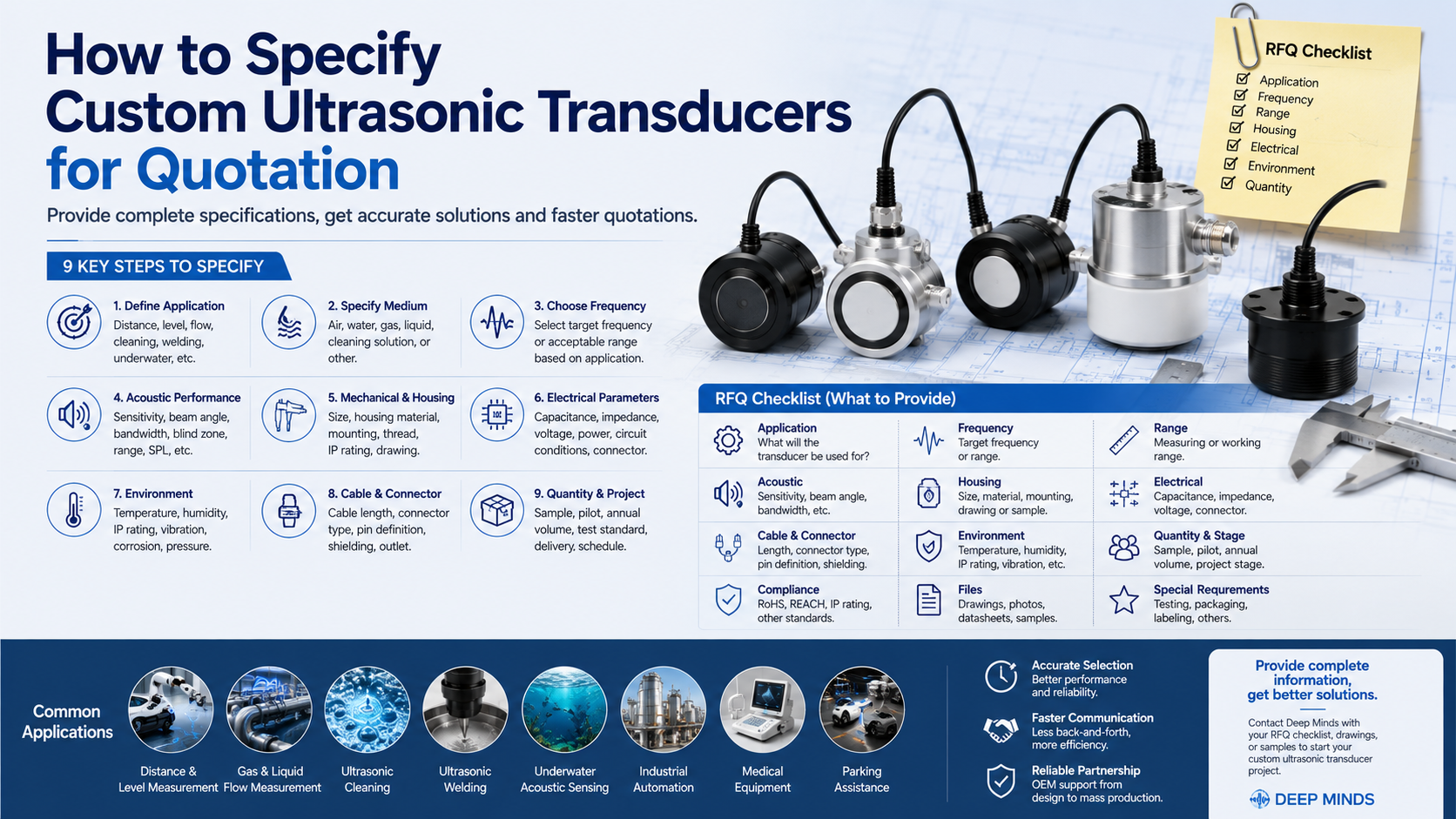
Custom Ultrasonic Transducer RFQ Checklist
The following checklist can be used when preparing a quotation request for standard or custom ultrasonic transducers. Providing this information helps the supplier evaluate the correct model, customization feasibility, sample plan, and pricing.
| RFQ Item | Information to Provide |
|---|---|
| Application | Distance, level, flow, cleaning, welding, underwater, medical, industrial, or OEM module |
| Medium | Air, water, gas, liquid, cleaning solution, plastic welding system, underwater environment, or other |
| Frequency | Target frequency or acceptable frequency range |
| Measuring or working range | Distance range, tank height, pipe size, flow range, operating depth, or working area |
| Acoustic requirements | Sensitivity, sound pressure level, beam angle, bandwidth, blind zone, directivity, or echo strength |
| Mechanical design | Size, housing, thread, mounting method, front face design, drawing, or sample |
| Electrical parameters | Capacitance, impedance, voltage, power, connector pins, and circuit condition |
| Cable and connector | Cable length, connector type, pin definition, shielding, waterproofing, and outlet direction |
| Environment | Temperature, humidity, IP rating, pressure, vibration, corrosion, indoor or outdoor use |
| Compliance | RoHS, REACH, IP rating, or project-specific standard requirements |
| Quantity | Samples, pilot quantity, annual forecast, and mass production volume |
| Project stage | Concept, prototype, replacement, redesign, pilot run, or mass production |
| Files | Drawings, photos, datasheets, existing samples, test reports, or installation drawings |
Common Mistakes When Requesting a Custom Transducer Quotation
Many quotation delays happen because the initial request is too vague. The following mistakes are common in custom ultrasonic transducer projects.
Only Providing the Frequency
Frequency is important, but it is not enough. A 40kHz distance transducer, a 40kHz cleaning transducer, and a 40kHz OEM sensing transducer may require completely different structures and performance levels.
Not Explaining the Application
The application determines whether the transducer should be designed for detection, measurement, cleaning, welding, flow, or underwater acoustic use. Without this information, the supplier can only guess the required structure.
Ignoring the Operating Medium
Air, water, gas, cleaning liquid, and underwater environments require different acoustic matching and housing designs. A transducer that works in air may not work correctly in liquid or high-pressure environments.
Not Providing Mechanical Limits
OEM products often have limited installation space. If the housing size, thread, cable direction, or connector location is not defined early, the sample may not fit the final device.
Forgetting Circuit Conditions
The transducer must match the driving and receiving circuit. If the circuit information is missing, the selected transducer may not reach the required output or sensitivity during testing.
Not Mentioning Environment and Reliability Requirements
Temperature, humidity, waterproofing, vibration, chemical exposure, and pressure can all affect reliability. These conditions should be included before the quotation stage, not after sample failure.
Not Providing Quantity or Project Stage
Sample pricing, tooling investment, and production planning depend on project volume. A prototype project and an annual mass production project are evaluated differently.
Standard Model or Fully Custom Design?
Not every project needs a fully custom ultrasonic transducer. In many cases, a standard model can be used for early testing or even mass production. Custom design is recommended when the standard product does not meet mechanical, acoustic, electrical, or environmental requirements.
| Requirement | Standard Model | Custom Design |
|---|---|---|
| Fast sample testing | Usually better | Possible, but slower if new tooling is required |
| Special housing | Limited | Better |
| Low tooling cost | Usually better | Depends on design complexity |
| OEM integration | Possible if dimensions match | Better for restricted installation space |
| Special acoustic performance | Limited by existing models | Better when performance targets are clear |
| Mass production optimization | Possible | Better for stable high-volume projects |
A standard model is usually suitable when the frequency, size, housing, cable, and performance already match the application. A custom design is more suitable when the project requires special frequency, special housing, waterproof structure, custom cable, restricted installation size, or optimized OEM production.
How Deep Minds Supports OEM Ultrasonic Transducer Projects
Deep Minds supports standard and custom ultrasonic transducer projects for OEM customers, equipment manufacturers, engineering teams, and system integrators. The selection process can start from an existing standard model, a customer drawing, an existing sample, or a new application requirement.
Support may include:
- Standard model recommendation
- Custom frequency evaluation
- Housing and mechanical structure customization
- Cable and connector customization
- Waterproof or sealed structure design
- OEM sample development
- Application-based transducer selection
- Batch production support
Deep Minds works with ultrasonic transducers for distance measurement, level measurement, gas and liquid flow measurement, cleaning, welding, and underwater acoustic sensing. If your project already has drawings, samples, or test requirements, these can be reviewed together with the RFQ checklist.
FAQ
What information is needed for a custom ultrasonic transducer quotation?
Useful information includes the application, operating medium, frequency, measuring or working range, acoustic requirements, housing size, mechanical drawing, electrical parameters, cable, connector, environment, quantity, and project stage. Existing samples, photos, datasheets, and test reports are also helpful.
Is frequency enough to quote an ultrasonic transducer?
No. Frequency alone is not enough. Transducers with the same frequency may be designed for different applications, power levels, housings, sensitivities, beam angles, cables, and circuit conditions. The application and complete specification should be provided.
Can the cable and connector be customized?
Yes. For OEM projects, cable length, connector model, pin definition, shielding, waterproof connector, cable outlet direction, labeling, and packaging can often be customized according to the project requirements.
Can you quote based on an existing sample?
Yes. An existing sample can help evaluate size, housing, cable, connector, and possible replacement requirements. However, it is still recommended to provide the application, target performance, test condition, quantity, and any improvement requirements.
What is the MOQ for custom ultrasonic transducers?
The minimum order quantity depends on whether the project uses an existing structure or requires new tooling, special materials, custom cables, special connectors, or additional testing. MOQ should be confirmed after reviewing the specification.
How long does custom ultrasonic transducer development take?
Development time depends on specification complexity, tooling requirements, material availability, sample testing, customer validation, and production process. The schedule should be confirmed after the application, drawing, performance target, and sample requirements are reviewed.
Conclusion
A custom ultrasonic transducer quotation should include more than frequency. Application, medium, measuring range, acoustic performance, housing, electrical matching, cable, connector, environment, quantity, and project stage all affect the final design and pricing.
Providing complete RFQ information helps the supplier recommend a suitable standard model or evaluate a custom design more accurately. It also reduces communication time, improves sample success rate, and supports smoother OEM project development.
Contact Deep Minds with your application details, drawings, samples, or RFQ checklist to discuss a standard or custom ultrasonic transducer for your OEM project.