What Is an Ultrasonic Transducer for Distance Measurement?
An ultrasonic transducer for distance measurement is the acoustic component that converts electrical energy into ultrasonic sound waves and converts returning echoes back into electrical signals. In a distance sensing system, the transducer is responsible for transmitting sound into the air, receiving the reflected echo from a target, and determining whether the signal is strong and stable enough for accurate measurement.
It is important to distinguish an ultrasonic transducer from a complete ultrasonic sensor. A transducer is the core acoustic element, while a sensor or sensor module usually includes the transducer, driving circuit, receiving circuit, signal processing, housing, output interface, and calibration. For complete sensor-level selection, you can also read our ultrasonic distance sensor selection guide.
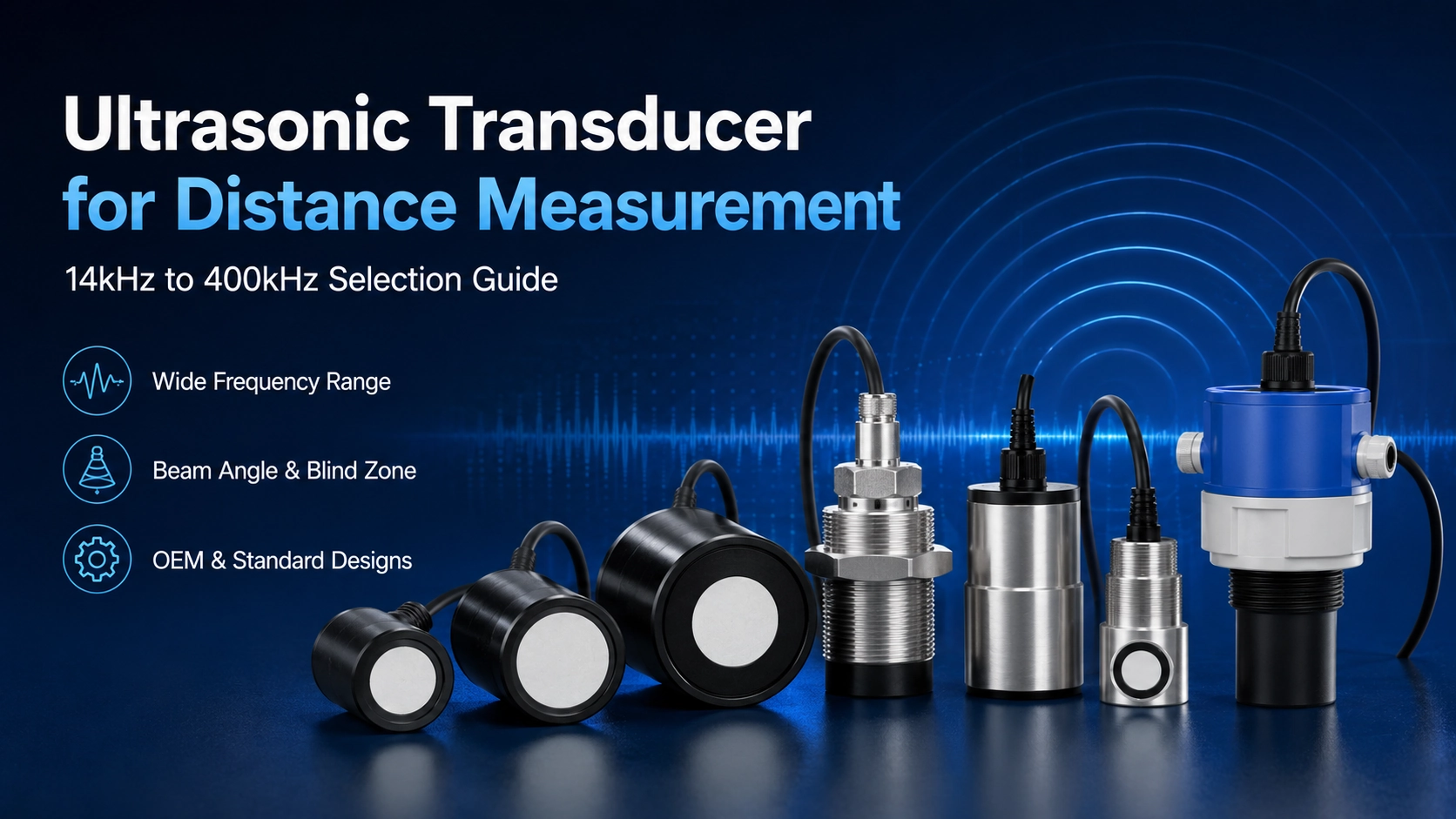
In OEM projects, selecting the right transducer is often the first step. Frequency, sensitivity, beam angle, blind zone, housing structure, and electrical matching all influence the final detection range and measurement reliability. Deep Minds provides ultrasonic transducers for distance measurement from 14kHz to 400kHz for industrial sensing, level measurement, obstacle detection, parking assistance, and customized distance sensing systems.
Ultrasonic technology generally refers to sound waves above the upper limit of human hearing. For a basic definition of ultrasonics, see this reference on ultrasonics.
How Ultrasonic Distance Measurement Works
Most ultrasonic distance measurement systems use the time-of-flight principle. The transducer emits an ultrasonic pulse toward a target. When the sound wave reaches the target surface, part of the acoustic energy is reflected back. The receiving transducer or transceiver detects the echo, and the system calculates distance based on the time delay between transmission and reception.
In a simplified system, the measurement process includes three steps:
- The driving circuit excites the ultrasonic transducer at or near its resonant frequency.
- The ultrasonic wave travels through air and reflects from the target surface.
- The receiving circuit detects the echo and the processor calculates the distance.
In actual applications, the final measurement performance depends on more than the time-of-flight formula. Target size, material, surface angle, environmental noise, air temperature, humidity, airflow, installation structure, and the acoustic behavior of the transducer all affect echo quality.
Why the Transducer Affects the Final Measurement Range
The transducer determines how efficiently ultrasonic energy is transmitted and received. A stronger sound pressure level can improve long-range detection, while higher receiving sensitivity helps detect weaker echoes. Beam angle determines the detection area, and ringing behavior affects the minimum measurable distance, also known as the blind zone.
This is why two systems using the same measurement principle can perform very differently if they use different transducer frequencies, housings, or circuit designs.
Frequency Selection: 14kHz to 400kHz Ultrasonic Transducers
Frequency is one of the most important parameters when selecting a distance measurement ultrasonic transducer. Lower frequencies generally propagate farther in air and are suitable for longer-range detection. Higher frequencies usually provide better resolution and more compact acoustic designs, but they attenuate faster in air and are more suitable for shorter-range or controlled applications.
For engineering background on ultrasonic sensing, frequency, and air attenuation, Texas Instruments provides useful technical material on ultrasonic sensing basics.
| Frequency | Typical Range Direction | Typical Applications | Selection Notes |
|---|---|---|---|
| 14kHz | Longer range | Long-distance detection, large target measurement, industrial sensing | Lower frequency, stronger propagation, wider beam, larger acoustic structure |
| 22kHz / 30kHz | Long to medium range | Outdoor detection, large object detection, industrial distance sensing | Suitable when longer air-based detection is required |
| 40kHz | General-purpose range | Parking sensors, object detection, level and distance systems | Common balance of range, cost, signal strength, and availability |
| 50kHz / 75kHz | Medium range | Industrial sensing, controlled detection, OEM modules | Useful when beam angle or mechanical size needs to differ from 40kHz designs |
| 112kHz / 125kHz | Medium to shorter range | Compact distance sensing, level detection, more directional systems | Better directionality and resolution than many low-frequency options |
| 200kHz | Shorter range / higher resolution | Compact devices, short-distance detection, controlled measurement systems | Higher attenuation in air; requires proper circuit and acoustic matching |
| 300kHz / 400kHz | Short range / specialized measurement | High-resolution short-range sensing, compact OEM designs | Best for controlled applications where short range and resolution are more important than maximum distance |
There is no universal “best frequency” for every distance measurement application. A 40kHz ultrasonic transducer may be suitable for many general-purpose systems, while a 14kHz or 22kHz model may be better for longer-range detection. For compact or higher-resolution short-range systems, 200kHz, 300kHz, or 400kHz options may be more appropriate.
Range, Beam Angle, and Blind Zone
When selecting an ultrasonic transducer for distance measurement, range should not be evaluated as a single number. The actual working range depends on the acoustic output, receiving sensitivity, target characteristics, installation conditions, and signal processing capability.
Measurement Range
The maximum detection range is influenced by frequency, sound pressure level, receiver sensitivity, target size, target material, and environmental conditions. A large, hard, flat target can usually reflect a stronger echo than a small, soft, angled, or irregular target.
For this reason, a transducer that performs well in laboratory testing may need additional evaluation in the final application environment. Industrial installations, outdoor locations, moving targets, and dusty or humid environments can all reduce practical detection distance.
Beam Angle
Beam angle defines the effective detection area of the ultrasonic wave. A wider beam can cover a larger area and tolerate some installation deviation, but it may also increase the chance of detecting side objects or unwanted reflections. A narrower beam can improve directional detection and reduce false echoes, but it requires more careful alignment.
For object detection, parking assistance, and obstacle avoidance, beam angle should be selected according to the target size and detection zone. For tank level or vertical distance measurement, the beam should be directed toward the target surface while avoiding walls, pipes, brackets, or internal structures.
Blind Zone
The blind zone is the minimum distance near the transducer where reliable measurement is difficult or impossible. After the transducer transmits a pulse, it continues to vibrate for a short period. During this ringing and settling time, the system may not be able to detect a returning echo accurately.
Short-distance applications should not only check the maximum measuring range. They must also confirm the minimum measurable distance, ringing behavior, and installation clearance.
Target Surface and Installation Conditions
The target surface has a direct effect on echo strength. Hard, flat, and perpendicular surfaces usually provide stronger reflections. Soft materials, foam, fabric, angled surfaces, curved objects, and irregular shapes can absorb or scatter ultrasonic energy, making detection more difficult.
Installation angle is also critical. If the ultrasonic wave hits the target at a steep angle, the echo may reflect away from the receiver instead of returning to it. In applications such as bin level measurement, tank monitoring, robotic detection, and industrial automation, the transducer should be installed with a clear acoustic path to the target.
The surrounding environment should also be considered. Nearby walls, machine frames, pipes, brackets, or protective covers may create false echoes. Airflow, wind, rain, condensation, dust, temperature changes, and acoustic noise can also affect measurement stability.
Housing and Mechanical Design Options
The housing of an ultrasonic transducer is not only a mechanical package. It affects acoustic output, beam pattern, waterproofing, installation stability, and long-term reliability.
Common housing and structure options include:
- Open-type ultrasonic transducers for controlled indoor applications
- Closed-type transducers for improved protection
- Waterproof transducers for outdoor, humid, or exposed environments
- Threaded housings for fixed industrial installation
- Metal housings for stronger mechanical protection
- Plastic housings for lightweight and cost-sensitive designs
- Custom cables, connectors, pins, and mounting structures
For OEM projects, the transducer housing should be reviewed together with the PCB layout, installation space, sealing method, target direction, and final product enclosure. A mechanically convenient design is not always acoustically optimal, so early evaluation is recommended.
Electrical Parameters to Confirm Before Selection
Electrical matching is another important part of transducer selection. Even when the frequency and housing appear suitable, poor circuit matching can reduce signal strength, increase noise, or make the measurement unstable.
| Parameter | Why It Matters |
|---|---|
| Resonant frequency | Affects range, attenuation, beam behavior, and resolution |
| Sound pressure level | Influences transmission strength and long-range detection capability |
| Receiving sensitivity | Determines how well weak echoes can be detected |
| Capacitance / impedance | Affects circuit matching and signal transfer efficiency |
| Drive voltage | Influences acoustic output and system power design |
| Beam angle | Controls detection coverage and false echo risk |
| Operating temperature | Affects reliability, sound speed compensation, and long-term stability |
| Housing and sealing | Determines installation method, protection level, and acoustic performance |
When possible, the transducer should be tested with the final driving circuit, receiving circuit, housing, and installation position. This helps confirm whether the selected model can meet the real measurement requirements instead of only matching the datasheet conditions.
Common Applications of Distance Measurement Ultrasonic Transducers
Distance measurement ultrasonic transducers are used in many systems where non-contact detection is required. Because ultrasonic sensing does not depend on target color or transparency in the same way as optical sensing, it is suitable for many industrial and environmental applications.
Industrial Object Detection
Ultrasonic transducers can detect objects on conveyors, production lines, packaging machines, and automation equipment. Frequency and beam angle should be selected according to object size, moving speed, and installation distance.
Parking Assistance and Vehicle Detection
40kHz ultrasonic transducers are widely used in parking assistance and short-range vehicle detection systems. These applications require stable short-range detection, appropriate beam coverage, and strong resistance to vibration, temperature change, and outdoor conditions.
Robot and AGV Obstacle Avoidance
Robots, AGVs, and service equipment use ultrasonic distance sensing to detect nearby obstacles. In these systems, response time, blind zone, beam angle, and installation height are especially important.
Level and Distance Measurement
Distance measurement transducers can also be used in liquid level, solid level, and container fill-level systems. For broader sensor selection across distance, level, flow, and underwater measurement, see our guide on how to choose an ultrasonic sensor.
Smart Bins and Container Monitoring
In smart waste bins and container fill-level monitoring, the transducer must work reliably in a compact space with irregular surfaces, changing target angles, and possible contamination. Waterproof or protected housing designs are often preferred.
Standard vs Custom Ultrasonic Transducer
A standard ultrasonic transducer is usually suitable when the required frequency, range, beam angle, housing size, and electrical parameters already match the application. Standard models are often used for prototype testing, general industrial detection, and applications with common installation requirements.
A custom ultrasonic transducer may be required when the project has special mechanical, acoustic, electrical, or environmental requirements. Customization may involve frequency, housing size, waterproof structure, cable length, connector type, beam angle, sensitivity, or mounting design.
Custom design is often recommended for:
- OEM distance sensor modules
- Products with limited installation space
- Outdoor or waterproof sensing systems
- Special frequency requirements
- High-temperature, low-temperature, humid, or dusty environments
- Applications requiring specific cable, connector, or mounting structures
- Batch production projects with defined mechanical drawings
How to Request a Quotation for a Distance Measurement Ultrasonic Transducer
To receive an accurate recommendation or quotation, it is useful to prepare the key application requirements before contacting the supplier. The more complete the information, the easier it is to select a suitable standard model or evaluate a custom design.
| Information Needed | Example Details |
|---|---|
| Application | Object detection, level measurement, parking assistance, robot obstacle avoidance, OEM module |
| Required measuring range | Minimum and maximum detection distance |
| Target object | Size, material, surface shape, movement, and reflection condition |
| Preferred frequency | 14kHz, 22kHz, 30kHz, 40kHz, 75kHz, 125kHz, 200kHz, 400kHz, or other |
| Blind zone requirement | Minimum measurable distance from the transducer face |
| Installation environment | Indoor, outdoor, humid, dusty, windy, high-temperature, low-temperature, or noisy environment |
| Housing requirement | Open type, closed type, waterproof, threaded, metal, plastic, or custom structure |
| Electrical requirements | Drive voltage, capacitance, sensitivity, connector, cable length, or circuit interface |
| Project stage | Prototype testing, sample evaluation, pilot run, or mass production |
| Drawing or sample | Mechanical drawing, existing sample, or installation space reference |
If the application is still in the early design stage, Deep Minds can help review the expected measurement range, frequency direction, housing requirements, and customization feasibility before sample selection.
FAQ
What frequency is best for ultrasonic distance measurement?
There is no single best frequency for all applications. Lower frequencies such as 14kHz, 22kHz, 30kHz, and 40kHz are often used for longer-range or general-purpose distance measurement. Higher frequencies such as 200kHz, 300kHz, and 400kHz are more suitable for shorter-range, compact, or higher-resolution applications. The final choice depends on range, target surface, beam angle, blind zone, housing, and circuit design.
What is the difference between an ultrasonic sensor and an ultrasonic transducer?
An ultrasonic transducer is the acoustic element that transmits and receives ultrasonic waves. An ultrasonic sensor is usually a complete device or module that includes the transducer, electronics, housing, output interface, and signal processing. In OEM projects, the transducer is often selected first and then integrated into the final sensor system.
Can one ultrasonic transducer both transmit and receive?
Yes. Some systems use one ultrasonic transducer as a transceiver, meaning it transmits the ultrasonic pulse and then receives the echo. Other systems use separate transmitting and receiving transducers. The best structure depends on the required range, blind zone, circuit design, installation space, and measurement accuracy.
Why does a higher-frequency ultrasonic transducer usually have shorter range in air?
Higher-frequency ultrasonic waves generally attenuate faster in air. This means the signal loses energy more quickly as it travels. As a result, high-frequency transducers are often used for shorter-range or more controlled applications, while lower-frequency transducers are often selected for longer-distance detection.
What information is needed for a custom ultrasonic transducer quotation?
For a custom quotation, it is helpful to provide the application, measuring range, target object, preferred frequency, blind zone requirement, working environment, housing size, waterproof requirement, cable and connector needs, electrical parameters, sample quantity, and estimated production volume. Drawings or existing samples can also help speed up evaluation.
Conclusion
Selecting an ultrasonic transducer for distance measurement requires more than choosing a frequency or checking the maximum range. Frequency, beam angle, blind zone, target surface, housing design, electrical matching, and installation environment all affect the final measurement performance.
Deep Minds provides standard and custom ultrasonic transducers from 14kHz to 400kHz for distance measurement, level sensing, object detection, parking assistance, robot obstacle avoidance, and OEM sensing systems.
Contact Deep Minds to discuss a standard or custom ultrasonic transducer for your distance measurement application.