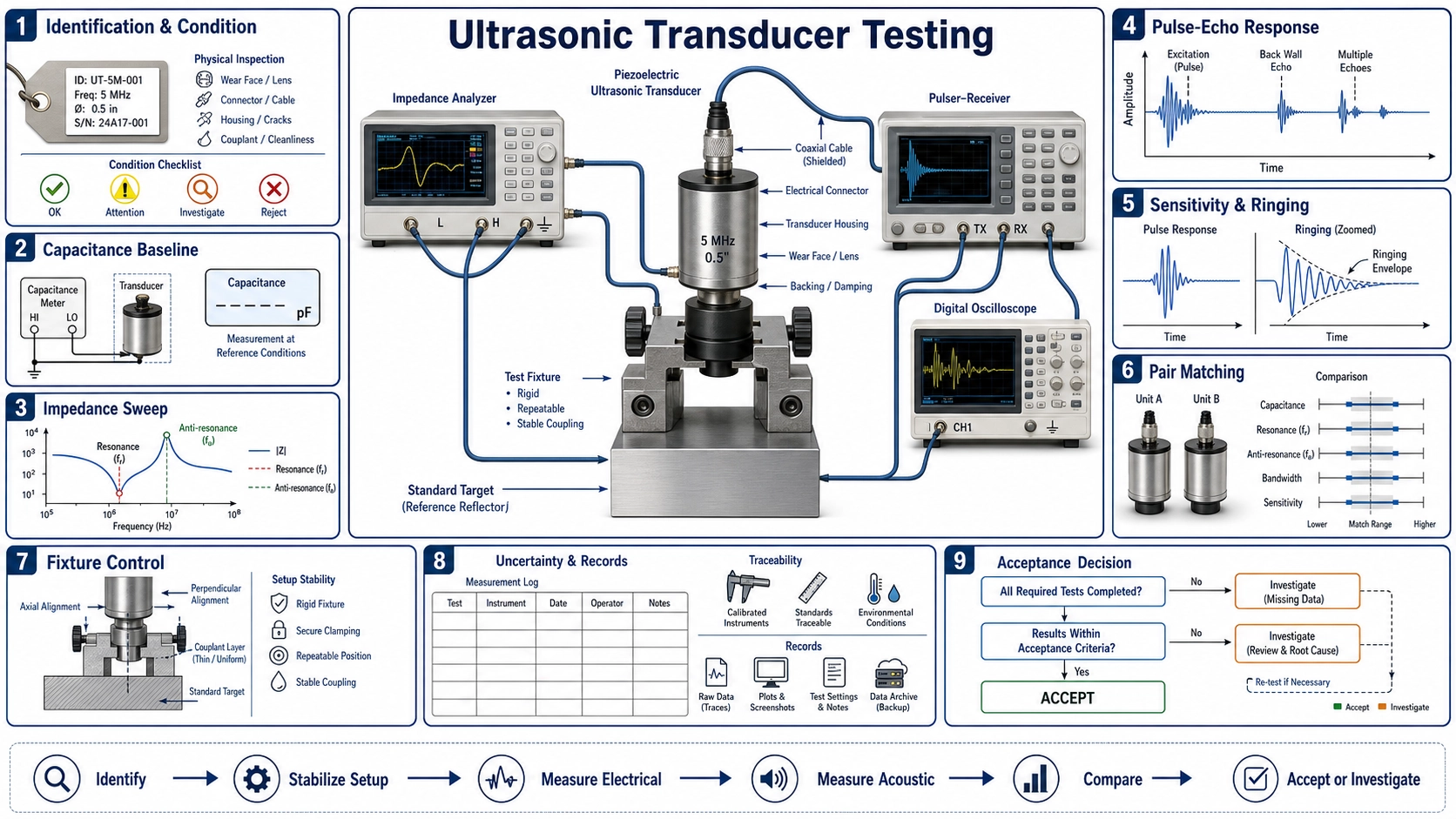
Define the decision before choosing the test
An ultrasonic transducer cannot be accepted or rejected from its frequency label alone. “40 kHz” may describe a nominal operating region, while the measured resonance, impedance, bandwidth, sensitivity, and decay depend on construction, mounting, cable, temperature, acoustic load, and test method. A useful test plan begins with the decision it must support: incoming inspection, supplier comparison, circuit design, matched-pair selection, production screening, or failure analysis.
The same measurement should not be stretched across all those decisions. An electrical impedance sweep is valuable for identifying resonances and loading, but it does not by itself prove acoustic output or receive sensitivity. A pulse-echo waveform reveals system ring-down, but it includes the driver, fixture, target, medium, receiver, and threshold. This guide shows how to separate the measurements and document their boundaries.
Create a controlled test identity
Assign every sample a unique identifier and record part number, lot, date, cable and connector, housing, visible markings, intended frequency, and conditioning history. Photograph the face, terminals, strain relief, and any damage. Allow samples and test equipment to reach a defined laboratory condition before comparison. Piezoelectric and polymer properties can change with temperature, and moisture or a recent thermal exposure can add uncontrolled variation.
Record the exact instrument model, calibration status, fixture, lead compensation, drive level, sweep settings, oscilloscope bandwidth, sampling, termination, target, distance, medium, and software calculation. Without these conditions, two values with the same unit may not be comparable.
Test sequence and what each result means
| Test | Primary output | Useful decision | What it does not prove alone |
|---|---|---|---|
| Visual and mechanical inspection | Damage, dimensions, lead and housing condition | Identity and workmanship screening | Electrical or acoustic performance |
| Static capacitance and loss | Capacitance and dissipation under stated conditions | Gross consistency and driver current estimate | Resonance, sensitivity, or usable range |
| Impedance sweep | Magnitude, phase, resonance/antiresonance features | Circuit matching, assembly consistency, anomaly detection | Absolute sound pressure or receive sensitivity |
| Transmit/receive or pulse-echo | Waveform amplitude, timing, spectrum, signal-to-noise | Acoustic function in a defined fixture | Performance in a different target, medium, housing, or circuit |
| Ring-down measurement | Decay envelope and recovery time | Blind-zone and receiver recovery assessment | A universal blind zone independent of threshold and target |
| Environmental or life screening | Change before/after a defined stress | Robustness of the tested design and process | Compliance with a standard not actually followed |
1. Visual, dimensional, and continuity checks
Inspect for cracks, dents, loose housings, delamination, contaminated faces, damaged potting, pin movement, broken strain relief, corrosion, and inconsistent labels. Measure only dimensions that affect the interface or acoustic geometry, using an instrument appropriate to the tolerance. A transducer face should not be pressed or scraped merely to “check” it.
Perform continuity or insulation checks only at a safe level specified for the device. A piezoelectric element is capacitive; an ohmmeter response can be transient and is not a sensitivity test. Protect sensitive receive devices from electrostatic discharge and do not apply an insulation test voltage unless the construction and specification permit it.
2. Measure capacitance under stated conditions
State the measurement frequency, test voltage, temperature, connection mode, and whether the attached cable is included. Cable capacitance may be a significant fraction of a small transducer’s value. Open/short compensation at the fixture plane helps remove lead effects, but the compensation procedure and reference plane must be recorded.
Capacitance supports driver design because reactive current rises with frequency, voltage, and capacitance. It can also expose gross assembly differences. It should not be used as a substitute for a frequency sweep: two samples can have similar capacitance and different motional behavior.
3. Sweep complex impedance, not one spot frequency
Use an impedance analyzer or network analyzer configuration suitable for the expected impedance. Calibrate or compensate at the fixture reference. Select a sweep wide enough to include the expected resonance and neighboring modes, with enough points to resolve the features. Keep drive level low enough to avoid heating or nonlinear behavior unless high-level characterization is explicitly required.
Save impedance magnitude and phase, not only the minimum value. Identify resonance and antiresonance consistently according to the adopted model and reporting rule. A complete assembly may show structural or housing modes in addition to the intended mode. Compare curve shape, frequency, minimum impedance, phase transition, and repeatability after reconnecting the sample.
Mounting changes the result. A bare element, potted sensor, clamped housing, bonded device, air-loaded transducer, and water-loaded transducer are different systems. The test fixture should reproduce the condition relevant to the decision or explicitly state that it is an incoming electrical screen.
4. Build a reproducible acoustic fixture
For an air transducer, a transmit-receive bench can use a fixed coaxial separation, rigid mounts, controlled orientation, and an absorber or gated time window to reduce room reflections. For pulse-echo, use a stable target with defined material, size, angle, and distance. For immersion devices, control water path, temperature, degassing, alignment, and boundary reflections. Never compare air and immersion results as if the loading were the same.
Choose one reference driver waveform: voltage at the transducer terminals, frequency, burst cycles, repetition rate, and source impedance. Monitor the actual terminal waveform rather than assuming the generator setting reaches the device unchanged. On receive, fix gain, bandwidth, filtering, termination, and sampling. If a protection or transmit-receive switch is used, include it in the system test and document its recovery.
The existing ultrasonic transducer circuit matching guide explains how capacitance, resonance, drive voltage, receiver protection, and ring-down interact. The fixture here should be designed so those circuit variables remain controlled while samples are compared.
5. Report sensitivity as a defined comparison
“Sensitivity” is incomplete unless the test defines transmit, receive, or combined pulse-echo sensitivity and the reference quantity. A production screen may compare received peak or RMS voltage against a qualified reference transducer under identical geometry. A calibrated acoustic measurement may report pressure or receive response using traceable equipment and a stated uncertainty. Do not convert a relative bench voltage into an absolute sound-pressure claim without the required calibration.
Use a time gate that isolates the intended direct arrival or echo. Save the full waveform and spectrum, not only the peak. A narrow peak can change with one sample of timing; an energy or RMS window may be more robust when justified. Repeat after removing and replacing the sample to quantify fixture reproducibility.
6. Measure ring-down and recovery in the time domain
Ring-down is the residual electrical and mechanical response after excitation. Define the burst, terminal voltage, receiver chain, target, and threshold used to measure decay. Report the envelope or time for the response to fall below a stated level. The practical blind zone also depends on target reflectivity, propagation time, transmit-receive switching, amplifier recovery, filters, and detection threshold; it is not a transducer-only constant.
Distinguish acoustic echoes from electrical feedthrough. Repeat the test with an absorber, altered target distance, or separated transmitter and receiver where appropriate. A feature that moves with target distance is acoustic; one fixed to the drive timing may be electrical or structural. Use safe oscilloscope probing and differential measurement when the driver is floating or high voltage.
7. Pair transducers using the application metric
Matched pairs should be matched for the property that matters to the system. Frequency proximity alone may be insufficient if amplitude, bandwidth, phase, transit delay, or temperature tracking drives the measurement. For a reciprocal transmit-receive pair, test both directions where practical. For gas or liquid transit-time metering, pair selection may also need stability across pressure, temperature, and the final acoustic path.
Define the pairing algorithm before viewing production results. For example, set permitted differences in selected electrical features and in a controlled acoustic response. Preserve each unit’s data and pair identity. Avoid cherry-picking pairs from a small sample without confirming that future production can maintain the same distribution.
Acceptance limits need evidence
Build limits from design requirements, measurement capability, qualified reference samples, and process data. A golden sample is useful only if its stability is monitored; it can age, absorb moisture, suffer handling damage, or drift with the fixture. Include a control sample at the start and end of a test run and trend its result.
Estimate repeatability by repeated measurements without remounting, then reproducibility by different operators, fixtures, days, and remounts as appropriate. A tolerance narrower than the test system’s variation will reject good parts and accept uncertain ones unpredictably. Record calibration, uncertainty, guard bands, retest rules, and disposition of nonconforming samples.
Information to send with samples
- Application, medium, target or acoustic path, intended frequency and bandwidth.
- Transmit waveform, terminal voltage, cycles, repetition, duty cycle, and source impedance.
- Receive chain, gain, bandwidth, threshold, timing requirement, and maximum ring-down.
- Housing, mounting, cable, connector, sealing, temperature, pressure, and chemical environment.
- Required electrical and acoustic tests, conditions, sample quantity, statistics, and acceptance rule.
- Whether the request concerns loose elements, completed transducers, matched pairs, or the full system.
For a new design or quotation, combine this test information with the custom ultrasonic transducer RFQ checklist. For application-specific validation, compare the non-invasive ultrasonic air bubble sensor integration guide and the ultrasonic double-sheet detection guide. Deep Minds Ultrasonic cannot infer a production acceptance limit from a frequency label and photograph alone.
FAQ
Is the lowest impedance frequency the operating frequency?
Not automatically. The chosen operating point depends on the impedance and phase curve, acoustic response, loading, driver, receiver, bandwidth, and system objective. Define how resonance is reported and validate the complete assembly.
Can capacitance identify a defective transducer?
It can detect some gross differences, open circuits, or assembly changes, but similar capacitance does not prove equal motional or acoustic performance. Use it as one screen in a broader plan.
How should two transducers be matched?
Match the metrics that affect the application, which may include frequency features, impedance, amplitude, bandwidth, delay, phase, and temperature behavior. Test both directions if the system uses reciprocal operation.
Why do two laboratories report different sensitivity?
They may use different fixtures, distances, media, drive levels, gains, gates, targets, reference sensors, or calculations. Compare the full method and uncertainty before comparing the final number.
Technical references and test review
The NDE-Ed ultrasonic transducer characterization material illustrates the need to define beam and frequency-response measurements, while the Evident ultrasonic transducer technical notes provide additional background on transducer characteristics. Apply only methods relevant to the transducer type and application being tested.
For a test-plan review, send Deep Minds Ultrasonic the application, sample construction, medium, fixture drawing, equipment, excitation, receive settings, raw impedance files, waveforms, environmental conditions, repeatability data, and proposed limits. Raw curves and conditions are necessary; a spreadsheet of pass/fail labels is not enough to diagnose the design or process.