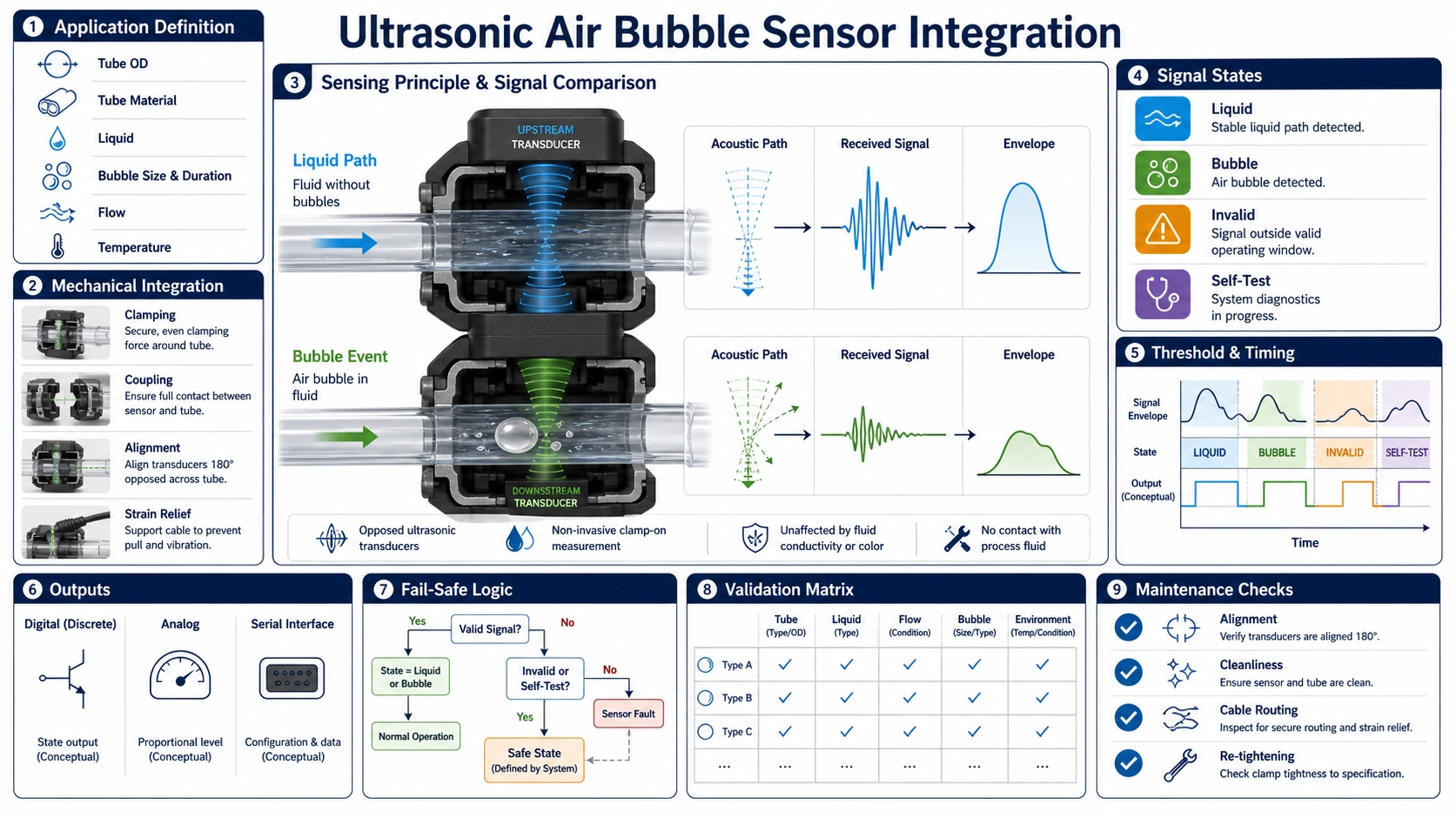
A bubble sensor detects an acoustic state, not a universal bubble size
A non-invasive ultrasonic air bubble sensor clamps around a tube and evaluates acoustic transmission without contacting the fluid. Liquid generally couples ultrasound across the tube differently from air. The electronics uses that contrast to classify liquid, air or bubble, empty tube, or another defined state. The detection threshold is therefore a property of the complete tube-fluid-sensor-electronics assembly, not a universal bubble diameter printed independently of test conditions.
Successful integration starts by defining the event that the machine must detect and the action it must take. A long air column, a train of small bubbles, foam, an incompletely wetted tube, and an empty tube can produce different time signatures. The system designer must also define permitted false alarms, missed-event risk, response time, startup state, self-test coverage, and what happens if the sensor, cable, or controller fails.
How the acoustic path changes
In a typical through-transmission arrangement, one transducer sends across the tube and another receives. Interfaces between sensor, tube wall, liquid, and any air region reflect and transmit energy according to their acoustic properties. When liquid fills the sensing section and wets the wall, the received signal follows one distribution. An air gap or bubble interrupts much of the liquid path and changes amplitude, waveform, timing, or correlation.
The sensor does not “see” a photographic outline. It observes a waveform through a three-dimensional volume. Bubble position, length along the tube, cross-sectional coverage, shape, motion, breakup, and wall adhesion matter. So do transmitter frequency, aperture, clamping pressure, tube ovality, receive bandwidth, gain, threshold, and sampling rate.
Define the detection requirement in measurable terms
| Requirement | Questions to answer | Evidence needed |
|---|---|---|
| Bubble event | Minimum air-column length or volume? Single bubble, accumulated air, foam, or empty tube? | Controlled event generation and independently measured reference |
| Flow condition | Minimum and maximum flow, stop-flow state, pulsation, pressure, and orientation? | Tests across the operating hydraulic envelope |
| Decision timing | Maximum detection delay, debounce, persistence, and reset? | Synchronized reference and output timing |
| Error behavior | Permitted false positives and false negatives? What state is safe on power or cable loss? | Risk analysis and fault-injection tests |
| Lifecycle | Tube replacement, lot variation, cleaning, ageing, condensation, and service interval? | Representative production and ageing samples |
For a safety-related function, these values must come from the complete equipment risk process. A component test cannot establish that the finished medical, laboratory, industrial, or dispensing system is safe or compliant.
Tubing is part of the sensor
Specify tube manufacturer and grade, material, outside and inside diameter, wall thickness, hardness, colour or filler where relevant, reinforcement, surface finish, and tolerances. Two tubes with the same outside diameter can transmit differently because the wall and formulation differ. Ageing, sterilization, cleaning chemicals, plasticizer loss, kinking, and repeated insertion can change geometry and acoustic loss.
The sensor channel must constrain the tube repeatably without crushing it or allowing motion. If the channel supports several sizes, define the insert, lid, spring, or clamp state for each. Tube ovality and seam orientation can affect the path. Marking a required rotational orientation may improve repeatability but adds an assembly control that must be designed and inspected.
Deep Minds Ultrasonic offers the BBMU-BD-A non-invasive bubble sensor, the BBMU-BD-B multi-size bubble sensor, and the BBMU-BD-C ultrasonic bubble detection component. Use their individual supported tubing and electrical documentation; do not transfer a tube range or threshold from one construction to another.
Liquid, wetting, and process state
Record liquid composition, temperature, viscosity, suspended material, gas solubility, conductivity where relevant to the equipment, and any formulation change. The acoustic response can shift between water, saline solution, oil, concentrated solution, emulsion, and liquid containing particles. A calibration with water does not automatically qualify another fluid.
Initial filling can leave an unwetted wall or small attached bubbles that differ from a moving air column. Priming rate, tube orientation, pump pulsation, back pressure, and fittings upstream influence bubble shape. Foam creates alternating liquid and gas interfaces and may need its own classification rather than being treated as one bubble. Test startup, steady flow, stop-flow, drain, refill, and expected cleaning states.
Mechanical integration and acoustic coupling
- Locate the sensor where the tube remains fully seated and is not pulled sideways by connectors, bends, or a moving pump head.
- Respect the allowed tube orientation and flow direction if the design specifies one.
- Keep the sensing channel clean and dry unless a specified coupling material is part of the design.
- Control lid closure, clamp force, insert identity, and cable strain relief.
- Separate the assembly from strong mechanical shock, continuous vibration, ultrasonic cleaners, and other acoustic sources where they affect the tested response.
- Prevent condensation or fluid leakage from creating an unintended coupling path around the tube.
- Make tube replacement unambiguous and inspectable; a partly closed lid should create a detectable fault or be mechanically prevented.
Thresholds, timing, and state logic
Preserve a raw signal or diagnostic value during development. Collect distributions for valid liquid, target bubble events, smaller non-target events, empty tube, no tube, misloaded tube, and known faults. Set thresholds from separation between these populations with allowance for component, tube, liquid, temperature, supply, and lifecycle variation. A threshold chosen from one “good” and one “bad” sample has no production margin.
Define sample rate and filtering relative to bubble speed and sensing length. A fast bubble may cross between slow samples; an overly long debounce can merge events or miss a short air column. Conversely, reacting to one noisy sample can create false trips. Use a state machine with explicit entry, persistence, exit, and invalid-signal rules. Record whether the output is level, pulse, latched alarm, or serial status.
Electrical interface and failure handling
Confirm supply range, current, startup time, output type, active polarity, pull-up or load, logic levels, response timing, cable length, connector, grounding, shielding, and electromagnetic environment. Define the controller interpretation during power-up, warm-up, self-test, disconnected cable, short circuit, out-of-range diagnostic, and loss of communication.
A self-test may exercise electronics or transducers, but its coverage must be stated. It may not prove that the correct tube is installed, that the liquid path is wet, or that the threshold detects the required bubble. Use fault injection to verify what is and is not detected. Do not describe a normal output as “fail-safe” without an architecture and risk analysis that demonstrates the claim.
Validation matrix
Create reference bubbles with a method whose uncertainty is appropriate to the requirement. Record bubble volume or axial length, generation method, flow, pressure, temperature, tube, liquid, orientation, and high-speed or synchronized reference where needed. Natural bubbles alone are not repeatable enough for establishing a threshold.
| Factor | Levels to include | Failure revealed |
|---|---|---|
| Tube | Minimum/nominal/maximum dimensions, multiple lots, aged and replaced samples | Poor fit, acoustic loss, production variation |
| Liquid | Approved formulations, temperatures, particles, degassed and gas-loaded states | Threshold shift and wetting differences |
| Air event | Below-target, target, above-target, long column, bubble train, foam, empty tube | Detection boundary and classification ambiguity |
| Hydraulics | Stopped, minimum, normal, maximum, pulsating, pressure limits | Event deformation and timing loss |
| Assembly | Repeated insertion, rotation, closure force, misload, cable movement | Mechanical reproducibility and invalid-state coverage |
| Environment | Temperature, humidity/condensation, supply, vibration, electromagnetic tests required by the product | Drift, false events, and electrical susceptibility |
Use separate development and confirmation samples where possible. Report detection probability and false-event rate over the defined matrix rather than only a single sensitivity number. For incoming and production characterization of the acoustic elements, apply the ultrasonic transducer testing framework.
Production and service controls
- Control sensor, tube insert, firmware and threshold revisions.
- Use qualified liquid and air references or an equivalent end-of-line fixture with monitored stability.
- Track raw diagnostic distributions, not only pass/fail counts.
- Define tube installation instructions and operator inspection points.
- Specify cleaning materials and prohibit residues that create an acoustic bridge.
- Store fault codes and event timing needed for service diagnosis.
- Revalidate after tube, liquid, pump, sensor, firmware, threshold, enclosure, or cable changes.
FAQ
What is the smallest bubble an ultrasonic sensor can detect?
There is no universal size independent of tube, liquid, bubble geometry, flow, frequency, electronics, threshold, and validation method. Define the required event and test it in the final assembly.
Can one calibration work for different tube materials?
Not without evidence. Wall thickness, acoustic properties, hardness, fit, and manufacturing variation change transmission. Each approved tube construction needs validation.
Can the sensor distinguish foam from one air bubble?
It may produce different time patterns, but classification requires suitable sampling and an algorithm validated on representative foam and bubbles. A binary threshold alone may not distinguish them reliably.
Does a self-test prove that bubble detection works?
Only to the extent defined by the self-test coverage. Electronic or transducer checks may not verify tube loading, wetting, fluid, event threshold, or the controller’s final protective action.
Technical references and integration request
For additional examples of non-invasive acoustic sensing, see the official overviews from TE Connectivity and SONOTEC. Their product claims apply to their own configurations; they illustrate why tube, fluid, event, and test conditions must accompany a detection specification.
For a Deep Minds Ultrasonic integration review, send tube drawings and samples, liquid formulations, bubble definition, flow and pressure range, orientation, timing requirement, false-event requirement, supply and interface, fault behavior, environment, regulatory context, validation method, and quantity.