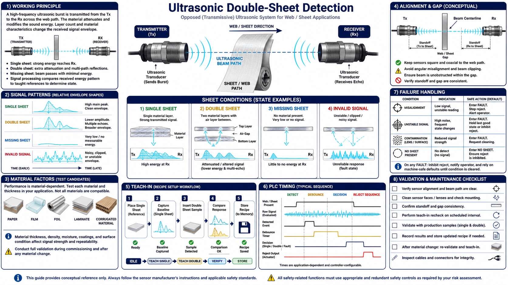
Double-sheet detection is a classification measurement
An ultrasonic double-sheet sensor places a transmitter and receiver on opposite sides of the material path. The acoustic signal crossing no sheet, one sheet, and two sheets changes because each air-material interface transmits, reflects, and attenuates energy differently. The controller classifies the received response as missing sheet, single sheet, double sheet, or an invalid condition.
The useful output is not a generic thickness measurement. It is a reliable decision among defined material states while sheets move, flutter, overlap, wrinkle, change lot, or carry print and coatings. A threshold that works on one paper stack may fail on a plastic film, metal foil, corrugated board, adhesive label, wet sheet, or a new material batch. The application must be taught and validated with representative samples.
Why ultrasound can distinguish layers
Air and solid materials have very different acoustic impedances. When airborne ultrasound encounters a sheet, only part of the energy passes through. A second sheet introduces more interfaces and often a thin air layer between sheets, changing the received amplitude, waveform, phase, or correlation. A missing sheet produces another response. The exact separation depends on material, thickness, porosity, stiffness, coating, surface texture, frequency, angle, sensor geometry, and electronics.
Sheets pressed together without an air gap can be more difficult to distinguish than loosely separated sheets. Conversely, a wrinkled single sheet can create variable angle and path length that resembles a double-sheet response. The sensor is therefore measuring the acoustic condition of the stack, not counting visible edges.
Define all machine states
| State | Physical examples | Required machine action | Validation concern |
|---|---|---|---|
| Single sheet | Normal material within approved lot and thickness range | Permit feed or continue process | Variation from print, coating, moisture, angle, and speed |
| Double sheet | Two complete sheets, partial overlap, label-on-liner, folded edge | Stop, reject, divert, or alarm according to risk | Minimum overlap time and smallest relevant double area |
| Missing sheet | Gap between sheets, failed pick, torn material | Wait, alarm, or synchronize the next cycle | Expected gap versus an unintended miss |
| Invalid signal | Misalignment, contamination, cable fault, blocked sensor, unsupported material | Defined fault state, not silently treated as single sheet | Diagnostic coverage and safe machine response |
Write the state table before selecting hardware. Some machines only need single versus double; others must also detect no sheet and sensor faults. The output logic and PLC program must preserve those distinctions.
Material qualification
Collect material name, manufacturer, grade, thickness range, basis weight where relevant, composition, porosity, reinforcement, coating, print coverage, surface texture, moisture, temperature, and lot variation. Include the thinnest, thickest, most porous, most heavily printed, wettest, and stiffest approved conditions. Do not qualify from one nominal coupon.
For multilayer products, define which combination is “single.” A label plus its release liner may be the normal single workpiece, while two such assemblies are the fault. A laminate can behave as one acoustically bonded structure. Corrugation changes path depending on flute orientation and local position. Metal and dense films may strongly attenuate airborne ultrasound and require a suitable sensor configuration or may lie outside the usable envelope.
Mechanical layout controls the signal
The emitter and receiver need a stable opposed geometry. Use the spacing, angular offset, and orientation approved for the selected sensor. Some systems intentionally use an angle to manage direct coupling or material behavior; do not assume perfectly normal incidence unless the manual specifies it. The sheet path must cross the intended sensing zone without striking either face.
- Mount both sensors on a rigid common structure so vibration does not change their relationship.
- Provide adjustment for alignment but lock it after commissioning.
- Keep enough clearance for worst-case sheet flutter, curl, seams, splices, and thickness.
- Avoid rollers, guides, air jets, suction cups, or machine frames that block or reflect the path.
- Place the sensing point where a double sheet persists long enough for the sensor and PLC to react.
- Protect faces from dust, fibres, adhesive, ink mist, oil, and impact while retaining service access.
- Route emitter and receiver cables away from moving parts and electrical noise sources.
Select and connect the sensor
The BBID-DSS ultrasonic double-sheet detection sensor is the Deep Minds Ultrasonic product format for opposed material-layer monitoring. Confirm its supported material and setup documentation for the intended sheet rather than inferring compatibility from “ultrasonic” alone.
Define supply range, startup, output type, active polarity, load, switching time, teach input, diagnostic output, connector, cable, grounding, and environmental protection. Decide whether the PLC sees separate single/double/no-sheet states, encoded outputs, or one switching output plus diagnostics. During power-up or invalid signal, the machine must enter a documented state.
Teach-in is a controlled calibration
Clean and align the system before teaching. Use approved single-sheet samples covering normal variation, then use representative double and missing states to confirm separation. If the sensor supports dynamic teach, control speed and sheet path. If it uses a manual threshold, preserve raw response distributions and document the selected margin.
- Record sensor identity, firmware or setting mode, mounting geometry, gap, angle, material and environmental condition.
- Measure the empty path and verify that its signal is stable.
- Run multiple single sheets from different positions and lots; capture minimum and maximum response.
- Run double sheets with relevant overlap, contact pressure, orientation, and speed.
- Confirm the missing-sheet state and any invalid-signal diagnostic.
- Set or execute teach-in, then repeat the samples without adjusting the mount.
- Save settings and define who may reteach the sensor and under what change control.
Do not reteach automatically whenever false alarms rise. Drift may indicate contamination, a loose bracket, a changed material, or electrical interference. Teaching a degraded state can erase the separation that protects the process.
Dynamic response and PLC timing
The acoustic classifier has a response time, and the PLC has scan, input-filter, logic, and actuator delays. At production speed, a partial overlap may remain in the beam only briefly. Calculate the available event time from sheet speed and the minimum double-sheet length that matters. Verify the complete chain with synchronized reference video or another suitable timing method.
Place the sensor far enough upstream for the machine to stop or reject, accounting for transport delay and stopping distance, but not so far that sheets can separate or shift before the action point. Define debounce and persistence without suppressing the shortest required event. If a sheet edge naturally passes through the beam, gate the decision using machine position rather than treating every edge as a missing sheet.
Validation matrix
| Factor | Test levels | Risk addressed |
|---|---|---|
| Material | Lots, thickness limits, colours, print, coating, moisture, temperature | Acoustic variation within approved production |
| Layer state | Missing, single, full double, partial overlap, fold, splice, label or seam | Boundary between normal feature and fault |
| Motion | Minimum/normal/maximum speed, start-stop, acceleration, flutter and skew | Insufficient event time and angular variation |
| Mechanics | Mount tolerance, vibration, clearance limits, repeated setup | Alignment and reproducibility |
| Environment | Dust, contamination, temperature, supply and required electromagnetic tests | Drift, false classifications and faults |
| Control chain | PLC scan, filters, communication, actuator delay and fault injection | Correct sensor output but late or unsafe machine action |
Use enough repetitions to estimate false-pass and false-reject behaviour for the defined process, including rare edge cases. Keep development samples separate from confirmation samples. A demonstration with a few hand-fed sheets is useful for feasibility, not sufficient for release to full production.
Troubleshooting by evidence
| Symptom | Checks | Controlled action |
|---|---|---|
| Single sheets intermittently rejected | Flutter, angle, print/coating, contamination, bracket vibration, supply | Trend raw diagnostic with machine position and material lot |
| Double sheets pass | Overlap duration, sheets pressed together, teach margin, PLC filtering | Reproduce the minimum relevant double at production speed |
| No stable state | Alignment, gap, cable, blocked face, unsupported material | Verify empty path, then one known reference without changing multiple variables |
| Works when stopped, fails in motion | Response time, flutter, vibration, electrical noise and gating | Synchronize sensor diagnostic, encoder and high-speed reference |
The ultrasonic transducer testing guide can be used to separate component response from fixture and electronics when a controlled bench investigation is required.
Maintenance and change control
- Inspect face cleanliness, bracket torque, alignment marks, cables, and protective guards.
- Use a qualified single/double/missing reference set for periodic functional checks.
- Trend diagnostic values so gradual drift is visible before classification fails.
- Control teach access and back up settings.
- Requalify after material, supplier, coating, speed, guide, sensor, firmware, PLC filter, or actuator changes.
- Document bypasses and prevent production from continuing indefinitely with the detector disabled.
FAQ
Can the sensor measure sheet thickness?
Double-sheet systems normally classify acoustic states rather than provide traceable thickness. The response relates to material and interfaces, not thickness alone.
Can one setting detect paper and plastic film?
Only if validation demonstrates adequate separation across both material envelopes. Different acoustic transmission often requires separate settings, recipes, or a different sensor arrangement.
Why are two sheets pressed together difficult to detect?
The interlayer air and interfaces often help create contrast. Tight contact or adhesive bonding can make the stack acoustically different from two loose sheets and must be represented in testing.
When should the sensor be retaught?
Only under controlled conditions after a qualified material or authorized setup change, or after evidence confirms the existing setting is no longer valid. Clean and inspect before reteaching.
References and application review
For additional technical background, see the Pepperl+Fuchs technology guide to ultrasonic double-material detection and the microsonic overview of material-layer detection. Their settings and claims apply to their products; use them as general principle references, not as BBID-DSS specifications.