Start with the inspection path, not the probe catalog
An ultrasonic NDT probe is one part of a measurement chain that also includes the test material, couplant or water path, instrument, scan method, reference standard, calibration block and acceptance procedure. A probe that produces a clean echo on a flat steel block can still be unsuitable for a weld, a rough casting or an automated immersion line. Selection should therefore begin with the defect orientation and the accessible inspection surfaces, then move to beam direction, frequency, element size and packaging.
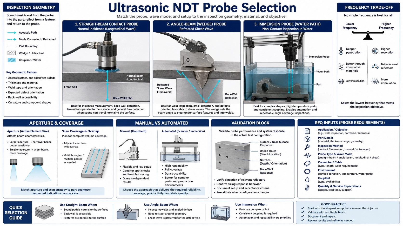
The practical first decision is geometric. Use a straight beam when the required sound path is approximately normal to the entry surface. Use an angle beam when the sound must enter at a refracted angle to intercept a weld or another planar discontinuity. Use immersion when a controlled water path, repeatable scanning position or non-contact coupling is central to the process. These are selection categories, not guarantees of detectability. The final procedure must be demonstrated on representative reference reflectors under the intended inspection conditions.
What the probe controls in an ultrasonic inspection
The probe converts an electrical pulse into an acoustic pulse and converts returning acoustic energy into an electrical signal. Its frequency spectrum, aperture, damping, construction and interface shape influence pulse length, penetration, beam spread, near-field structure and sensitivity to particular reflector sizes and orientations. The instrument settings cannot fully compensate for a fundamentally unsuitable beam path.
Probe choice also affects repeatability. A hand-held contact probe follows surface condition and operator pressure. A wedge fixes a nominal incident geometry but can wear and change the sound path. An immersion probe separates the element from the part with a water column, allowing mechanized positioning and stable coupling when water-path control is adequate.
Straight-beam contact probes
A straight-beam probe normally sends longitudinal sound approximately perpendicular to the contact surface. Typical tasks include locating laminations, checking plate or forging volume, measuring back-wall response and examining defects whose reflecting surfaces are favorably oriented to that beam. It is often the simplest configuration when one flat surface is accessible and the region of interest lies below it.
The BBND-GF contact ultrasonic flaw detection probe illustrates this product category. Its suitability for a real procedure still depends on the required frequency, element size, connector, wear-face geometry, test material and reference sensitivity. A strong back-wall echo alone does not prove that an unfavorably oriented crack can be detected.
Contact inspection becomes less stable on scale, uneven corrosion, tight curvature or surfaces that cannot retain a consistent couplant film. Smaller contact faces may follow curvature more effectively, while larger apertures can produce a different beam and near-field pattern. The trade must be tested rather than inferred from diameter alone.
Angle-beam probes for weld and directional inspection
An angle-beam assembly uses a wedge or another refracting interface to introduce sound at an angle, commonly as a shear wave in metal. This lets the beam interrogate weld volume and fusion faces from an accessible plate surface. Construction weld inspection commonly relies on angle-beam probes, often supplemented by straight-beam examination.
The selected refracted angle must fit the part thickness, weld geometry, scan surface and target orientation. Skip distance and sound path determine which zones can be covered from a given probe position. Frequency and aperture affect resolution, penetration and beam profile, while wedge material, temperature and wear affect the actual entry geometry. The BBND-WI angle-beam weld inspection probe is a relevant form when the procedure calls for angular insonification.
Do not select a nominal angle only because it appears in a familiar procedure. The applicable code, approved technique and calibration block may prescribe probe and wedge requirements. Where they do not, coverage should be plotted and verified with representative reflectors.
Immersion probes for controlled and automated scanning
Immersion inspection couples sound through a water bath or water column. The probe does not need to slide directly on the test surface, so scanners can control position, index, stand-off and incidence with high repeatability. Water delay also separates the interface echo from later part echoes when the setup is designed correctly. Focused probes may concentrate energy in a selected region, but focal behavior depends on frequency, aperture, water path and material refraction.
The BBND-AI automated immersion inspection probe represents this integration direction. The RFQ should not stop at “immersion probe.” It should define water path, scan axis, part contour, target zone, desired focus, fixture clearance, cable motion, pulser-receiver compatibility and the validation sample.
Immersion is not automatically superior to contact testing. It adds tanks or jets, water treatment, alignment, motion control and management of bubbles and surface curvature. Its value is repeatable coupling and automation when those variables are controlled.
Frequency, aperture and beam angle form one decision
| Input | Lower-frequency tendency | Higher-frequency tendency | What must be verified |
|---|---|---|---|
| Material and path | More useful penetration in attenuating or coarse material | More attenuation over the same path | Signal-to-noise on representative material |
| Reflector detail | Longer wavelength and generally less separation of close echoes | Shorter wavelength and potentially better resolution | Reference reflector response and pulse length |
| Aperture | Changes near field, divergence, footprint and focusing options | Coverage across the full scan volume | |
| Angle | Changes intersection with planar defects and accessible scan positions | Sound-path plot and calibration block | |
The phrases “lower frequency penetrates” and “higher frequency resolves” are useful tendencies, not standalone specifications. Grain structure, attenuation, surface roughness, noise, cable, pulser energy, filtering and acceptance threshold all influence the usable result. Compare candidate probes with the same instrument, controlled settings and reference target.
Match the probe to the workpiece and workflow
- Plate and forgings: define thickness, grain structure, entry faces and expected discontinuity orientation before choosing a straight or angled path.
- Castings: expect scattering and variable attenuation; a frequency that works on fine-grained steel may give poor signal-to-noise.
- Welds: provide weld preparation, thickness, heat-affected zone, scan surfaces and the governing procedure.
- Curved components: check contact footprint, wedge fit, index accuracy and mode conversion.
- Manual inspection: consider grip, cable exit, wear face, couplant and operator positioning.
- Automated inspection: add encoder geometry, probe holder, water path, scanning speed, channel count and repeatability criteria.
A controlled selection and validation sequence
- Define material, thickness, geometry, accessible surfaces and inspection temperature.
- Describe the target discontinuity by location, orientation and required reference reflector.
- Select the beam family: normal contact, refracted angle or immersion.
- Screen frequency and aperture using attenuation, resolution and coverage needs.
- Confirm wedge, delay, focus, connector and instrument compatibility.
- Plot the sound path and identify blind or poorly covered zones.
- Calibrate on the required block and record instrument, cable and probe identification.
- Demonstrate detection and sizing on representative samples, then freeze the approved setup.
Evident’s official angle-beam probe selection tutorial is a useful technical reference for the relationship between weld inspection, frequency, penetration and resolution. Project acceptance remains governed by the applicable procedure and code.
Information to include in an RFQ
Provide the material grade, thickness range, part drawing, surface condition, defect type and orientation, manual or automated method, contact or immersion environment, preferred frequency if procedure-controlled, element or footprint limits, nominal refracted angle where applicable, connector and cable, instrument model, temperature, applicable standard, reference block, quantity and required records. Deep Minds Ultrasonic can review these inputs through the engineering inquiry page; final selection should be confirmed by an approved drawing and sample validation.
FAQ
Can one straight-beam probe inspect every steel part?
No. Thickness, grain structure, geometry, target orientation, surface and required sensitivity change the usable beam and frequency.
Why is an angle beam commonly used on welds?
It can direct sound toward weld volume and planar fusion defects from an accessible adjacent surface. The correct angle and scan plan still depend on joint geometry and procedure.
Does immersion always improve sensitivity?
No. It improves coupling repeatability and positioning when the water path is controlled. Bubbles, misalignment, curvature and an unsuitable focus can reduce performance.
Should frequency be selected from thickness alone?
No. Thickness is one input. Material attenuation, grain, target size, sound path, pulse response and signal-to-noise must be evaluated together.