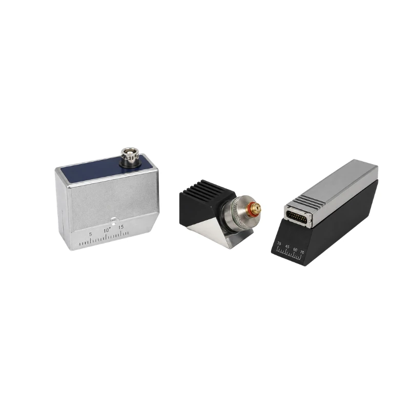
Product Overview
The BBND-WI is designed for ultrasonic inspection of welds in pipelines, pressure vessels, tanks, steel structures, bridges, rail components, and industrial equipment. It introduces ultrasound into the test material at a selected angle to detect cracks, lack of fusion, incomplete penetration, slag inclusions, and other discontinuities in the weld and heat-affected zone.
Multiple frequencies, inspection angles, element sizes, and wedge configurations are available for conventional welds, thick-wall components, small parts, restricted access areas, and selected elevated-temperature applications. Phased array configurations are available for electronic scanning and dynamic focusing.
Key Features
- Ultrasonic flaw detection for industrial welds and structures
- Multiple inspection angles and frequency options
- Options for large components, small parts, and restricted access
- Shear-wave and refracted longitudinal-wave inspection solutions
- Conventional single-element, dual-element, and phased array configurations
- Integral, replaceable, and elevated-temperature wedge options
- Suitable for manual inspection and scanner integration
Conventional Configuration Range
| Parameter | Available options |
|---|---|
| Product type | Ultrasonic weld flaw detection probe |
| Inspection method | Contact angle-beam inspection |
| Frequency | 1, 2, 2.25, 4, and 5 MHz |
| Inspection angle | 35°, 38°, 45°, 60°, 70°, 77°, 80°, and 90° |
| Element arrangement | Single or dual element |
| Probe body | Large, compact, or small |
| Wedge | Integral, replaceable, quick-change, or custom-curved |
| Connector | Lemo 1, Lemo 00, BNC, Microdot, or MMD |
| Elevated-temperature wedge | Selected configurations for short contact on surfaces up to 200°C |
Phased Array Configuration Range
| Parameter | Available options |
|---|---|
| Frequency | 1, 1.5, 2.25, 3.5, 5, and 7.5 MHz |
| Element count | 16, 32, 64, or 128 |
| Pitch | 0.25–3 mm |
| Elevation | 6–25 mm |
| Wedge | Flat or curved angle wedge and delay line |
| Scanning functions | Electronic angle control, focusing, and linear scanning |
Application Configurations
| Inspection task | Recommended configuration direction |
|---|---|
| General weld inspection | Standard body with multiple angle options |
| Thick-wall pipes and pressure vessels | Low-to-medium frequency with a larger element |
| Small welds and restricted access | Compact or small-body configuration |
| Coarse-grain and austenitic welds | Lower frequency, refracted longitudinal wave, or dual element |
| Elevated-temperature welds and structures | Elevated-temperature wedge |
| Multi-angle and wide-area inspection | Phased array configuration |
Typical Applications
- Pipeline girth-weld and longitudinal-weld inspection
- Pressure-vessel, tank, and boiler weld inspection
- Bridge and structural-steel weld inspection
- Rail, wheel, axle, and transportation-component inspection
- Inclined flaw detection in castings, forgings, and complex structures
- Austenitic-steel and coarse-grain weld inspection
- Aerospace structures and critical load-bearing components
Selection Parameters
Selection is based on the test material, weld type, wall thickness, joint geometry, inspection standard, required beam angle, frequency, scan coverage, wedge curvature, operating temperature, and instrument interface.
Compatible Equipment
- Conventional ultrasonic flaw detector or phased array instrument
- Probe cable
- Matching wedge
- Ultrasonic couplant
- Weld calibration block
- Manual or automated scanner
Operating Requirements
- Match the inspection angle and frequency to the weld geometry, material, and applicable inspection standard.
- Match the wedge contact surface to the component curvature and maintain stable coupling.
- Calibrate sound path, angle, sensitivity, and gain with an appropriate reference block before inspection.
- Follow the specified contact-time and cooling requirements for elevated-temperature configurations.