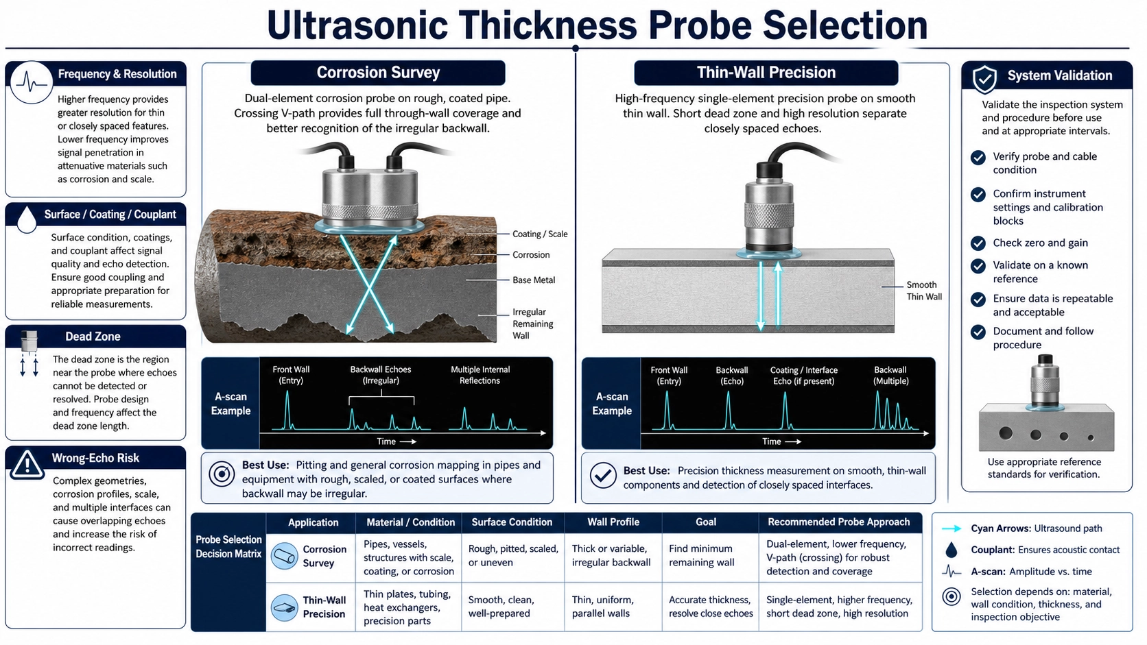
Two thickness tasks that should not share one default probe
Corrosion monitoring asks for the minimum remaining wall in a surface that may be rough, pitted, coated or curved. Precision thin-wall measurement asks the system to separate closely spaced echoes and measure a small, usually better-defined section. Both use ultrasonic time of flight, but they impose different requirements on the transducer, instrument, calibration and scanning method.
The correct starting question is therefore not “Which frequency is best?” It is “Which echo must be timed under which surface and material conditions?” A dual-element contact probe is commonly used for corrosion surveys because its transmit and receive elements form a crossing sound path below the entry surface. Precision measurements often use a single-element delay-line or other high-resolution configuration selected for the material and thickness range. Neither category guarantees a minimum thickness without testing the complete probe-and-gauge system.
How pulse-echo thickness measurement becomes a number
The gauge measures a time interval associated with echoes and converts it using the acoustic velocity assigned to the material. In the simplest idealization, thickness equals sound velocity multiplied by round-trip time and divided by two. Real systems must also handle probe delay, zero offset, V-path correction for dual elements, coating echoes, mode conversion, temperature-dependent velocity and echo selection.
An apparently stable digital value can still be wrong if the instrument locks onto the wrong echo. Good practice includes viewing or verifying the waveform where risk is high, calibrating on representative material and checking the result against known thicknesses near both ends of the intended range.
Corrosion and remaining-wall measurement
Corrosion inspection typically searches an area for local minima rather than measuring one ideal point. The outside surface may have scale or coating, while the inside surface can be irregular. A dual-element probe can improve near-surface behavior and reduce some interface effects, but it introduces a V-shaped sound path that requires the correct compensation. The contact footprint must also suit pipe curvature and pit scale.
The BBTM-CW corrosion and remaining-wall thickness probe is positioned for this task family. Selection still requires the material, expected remaining-wall range, pipe diameter, coating, surface preparation, temperature, scan density, couplant and gauge interface. Do not infer a measurable minimum or hot-surface rating from the application name.
During scanning, loss of coupling, bridging across a pit, echo doubling or an invalid early echo can hide a thin location or display an incorrectly high value. A survey procedure should define grid spacing, local rescans, waveform review, minimum capture, reference checks and how suspect readings are resolved.
Precision and thin-wall measurement
Thin walls produce short time separations between interface and back-wall echoes. The pulse must be short enough, and the instrument bandwidth and timing method suitable enough, to resolve the desired interval. Higher frequency often improves thin-section resolution, but it also increases attenuation and does not rescue poor coupling or unsuitable material.
The BBTM-PT precision thin-wall thickness probe represents this selection direction. A valid RFQ should include material, nominal and limit thicknesses, curvature, surface finish, layers, temperature, measurement repeatability target, available access and gauge model. Precision should be demonstrated on representative standards, not extrapolated from frequency alone.
Delay-line configurations can move the first usable echo away from the excitation pulse and can help with thin materials. Their maximum range may be more limited, and delay material changes with temperature. Very small contact areas can fit curved parts but demand careful alignment. These are system trade-offs rather than universal advantages.
Probe attributes and their practical consequences
| Attribute | Corrosion survey concern | Thin-wall concern | Verification |
|---|---|---|---|
| Element arrangement | Dual-element crossing path and V-path correction | Short pulse and clean echo separation | Known steps and waveform |
| Frequency | Penetration through rough or attenuating material | Resolution of closely spaced echoes | Signal-to-noise across range |
| Contact diameter | Curvature, pits and scanning coverage | Small feature access and alignment | Representative geometry |
| Wear face or delay | Durability and coupling on field surfaces | Near-surface timing and temperature drift | Zero and temperature checks |
| Instrument setup | Gain, blanking, V-path and minimum capture | Bandwidth, echo mode and resolution | Stored approved setup |
Surface, coating and couplant are measurement variables
Couplant replaces air at the probe interface, but more couplant is not always better. Its layer should be consistent, appropriate for the material and temperature, and compatible with the workpiece. Rust scale, loose coating, weld spatter and curvature can tilt or lift the probe. Surface preparation must be defined by the inspection procedure and asset constraints.
A coating may add a separate transit time. Some instruments and probe combinations support echo-to-echo or coating-specific modes, but that capability must be confirmed for the complete system. It is unsafe to assume every displayed value excludes coating. Likewise, sound velocity changes with material, alloy condition and temperature; calibration on a nominal generic velocity can create systematic error.
Dead zone and minimum measurable thickness
The dead zone is the interval in which the system cannot reliably separate a desired echo from excitation, interface response or ringing. Minimum measurable thickness is an application result for the complete system, not a property of the probe name alone. Evident notes that a dual-element probe used below its designed range can select invalid echoes and display an incorrectly high thickness.
Use the official ultrasonic thickness transducer selection guidance as a technical reference: material and thickness range lead the selection, corrosion commonly uses dual elements, and thin or attenuating materials drive different frequency choices. Validate the final combination experimentally.
Acceptance workflow for a probe-and-gauge combination
- Record probe, cable, instrument, software mode and setup revision.
- Condition the equipment and reference pieces at relevant temperature.
- Calibrate zero and velocity using representative material and thicknesses.
- Check at least a thin and thick reference within the intended range.
- Repeat with realistic curvature, coating and surface where applicable.
- Scan controlled artificial pits or steps and confirm the minimum is found.
- Review echo identity, repeatability and sensitivity to probe placement.
- Document rejection of loss-of-coupling and invalid-echo conditions.
Electrical and pulse-response checks can support incoming inspection and troubleshooting. The ultrasonic transducer testing guide explains impedance, sensitivity, ringing and pair comparison, but those bench tests do not replace thickness validation on material standards.
What to send with the inquiry
State whether the primary task is corrosion mapping, remaining-wall screening, production thickness control or precision thin-wall measurement. Include material, thickness range, geometry and minimum radius, surface and coating, temperature, required scan method, gauge model and connector, cable length, couplant restrictions, calibration standards, quantity and acceptance method. Submit these through the Deep Minds Ultrasonic contact page so the probe can be reviewed as part of the complete measurement chain.
FAQ
Is a higher-frequency probe always better for thin walls?
No. It often improves resolution, but attenuation, coupling, material and instrument bandwidth can limit the usable signal.
Can a corrosion probe measure through paint?
Only when the selected probe and instrument mode are validated for that coating and thickness range. Otherwise coating time may be included or the wrong echo selected.
Why can a stable reading still be wrong?
The gauge may be timing an interface multiple, noise or another unintended echo. Reference checks and waveform evidence are needed where the consequence is significant.
Should one probe cover the entire thickness range?
Not necessarily. A broad range, mixed materials or both corrosion and precision tasks may require more than one probe and approved setup.