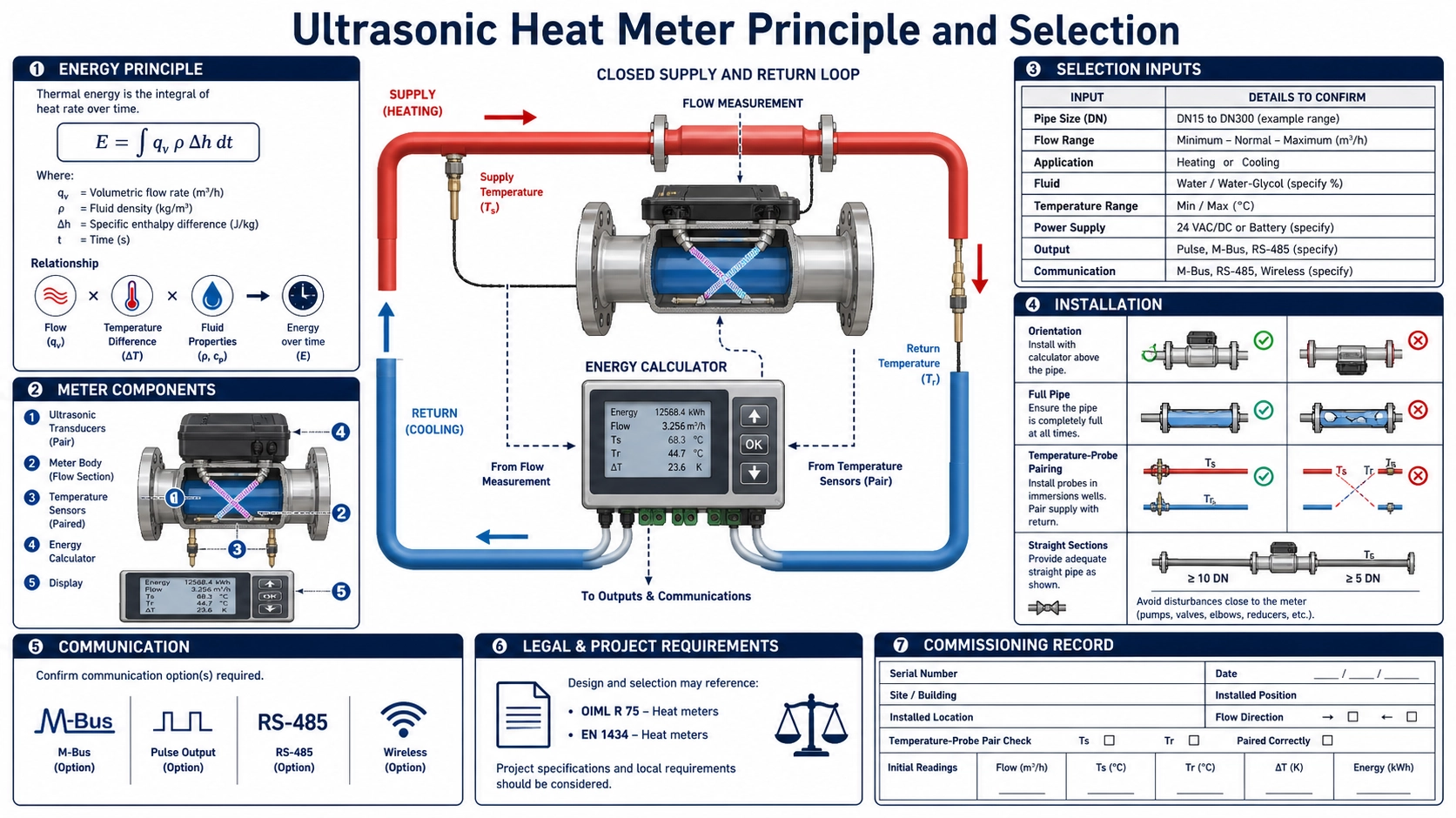
A heat meter is three measurements plus a calculation
An ultrasonic heating or cooling energy meter does not measure thermal energy with one sensor. It combines fluid flow, supply temperature, return temperature, and the thermophysical properties of the circulating fluid, then integrates the result over time. The flow channel can be accurate while the reported energy is wrong because the temperature sensors are reversed, poorly inserted, not matched, time-misaligned, or configured for the wrong fluid.
Selection must therefore treat the flow sensor, temperature-sensor pair, calculator, installation, communication, and regulatory purpose as one measuring system. A device for operational energy balancing is not automatically suitable for tenant billing or legal metrology. Confirm the applicable national rules, approved meter configuration, installation requirements, sealing, verification period, and data handling before procurement.
How thermal energy is calculated
A simplified instantaneous thermal-power relationship is:
thermal power ≈ volume flow × density × specific heat capacity × temperature difference
The meter integrates power over time to obtain energy. A complete calculator may use an enthalpy-difference formulation or tabulated properties as functions of temperature and fluid composition rather than constant density and heat capacity. The selected algorithm and fluid must match the system. Water, water-glycol mixtures, and other heat-transfer fluids cannot be treated as identical.
For heating, supply temperature is normally above return temperature; for cooling, the sign and channel naming may reverse according to the installation and calculator convention. Define whether energy is accumulated separately for heating and cooling, netted, or assigned by operating mode. A swapped pair can create negative values or put energy into the wrong register.
The measurement chain
| Element | Measured input | Typical error source | Commissioning evidence |
|---|---|---|---|
| Ultrasonic flow sensor | Volume or mass-related flow signal | Non-full pipe, gas, wrong direction, profile, pipe data, scaling | Flow diagnostics, direction, comparison, units and total |
| Supply temperature sensor | Fluid temperature at one side of the energy exchange | Poor immersion, wrong pocket, conduction, response lag, wiring | Location, insertion, sensor ID and reference comparison |
| Return temperature sensor | Fluid temperature at the other side | Pair swapped, unmatched response, installation asymmetry | Pair identity, channel assignment and simultaneous test |
| Calculator | Flow, temperatures, time and fluid properties | Wrong fluid, units, sampling, sign, clock, coefficient or firmware setup | Configuration record and independent calculation check |
| Communication/totalizer | Energy, volume, temperatures, alarms and time | Register scaling, rollover, reset, tariff mapping, lost intervals | End-to-end comparison at multiple values |
Why a small delta T is demanding
Energy is proportional to the temperature difference. When supply and return are far apart, a small absolute error in each temperature creates a smaller relative error in delta T. When the true delta T is small, the same sensor offsets, insertion differences, or response lag can become a large fraction of the measured difference.
For example, the uncertainty of a temperature difference is not simply the accuracy statement of one sensor. It depends on both sensors, their calibration correlation or matching, wiring, calculator resolution, installation, and dynamic response. Use a qualified matched pair when required and preserve the pair identity. Replacing only one sensor can invalidate the pair performance unless the approved procedure permits it.
During rapid load changes, flow and temperature samples must represent the same energy packet closely enough for the application. A fast flow signal combined with slowly responding or heavily filtered temperature sensors can bias transient energy. The calculator’s sampling and integration method therefore matters, not only steady-state specifications.
Select the meter configuration by application
| Configuration | Best fit | Key questions | Boundary to confirm |
|---|---|---|---|
| Residential inline meter | Apartment or terminal-unit heating/cooling measurement | Flow range, connection, pressure loss, temperature pair, display, communication | Local billing approval, orientation, installation length and verification |
| Prepaid/controlled meter | Projects combining metering with account or valve-control logic | Payment workflow, valve state, power, data security, fail state and audit trail | Legal, cybersecurity and utility process requirements |
| Fixed energy meter | Plant rooms, district loops, HVAC systems and larger pipes | Pipe range, flow technology, temperature inputs, outputs, enclosure and power | Permanent sensor locations and commissioning reference |
| Small-pipe clamp-on energy meter | Retrofit or non-invasive monitoring where supported | Pipe construction, full-pipe state, external flow sensing, temperature attachment and insulation | Whether the required accuracy or regulatory purpose permits external sensors |
Flow range and hydraulic conditions
Define minimum, normal, and maximum flow, not only nominal pipe size. Include zero periods, seasonal low load, pump staging, reverse flow, and startup. An oversized meter may spend too much time near its lower operating region, while an undersized meter can create unacceptable loss or exceed its rated range. For legal applications, use the flow definitions and metrological class required by the applicable approval.
Keep the pipe full and manage air. Follow the product’s permitted orientation and straight-run or flow-conditioning requirements. Locate the meter where pumps, control valves, mixing points, and branches do not create an unqualified profile. For external flow sensing, use the clamp-on ultrasonic flow meter installation guide and preserve signal diagnostics as part of commissioning.
Temperature sensor installation
Place supply and return sensors at locations that represent the same circuit flow used in the energy calculation. Avoid mixing points, dead legs, bypasses, and stratified headers unless the design accounts for them. Use approved pockets, direct-immersion fittings, surface assemblies, or other mounting. The two sides should have comparable thermal contact and response where the measurement method requires it.
- Preserve sensor-pair serial numbers and channel assignment.
- Use the specified insertion depth and heat-transfer material where permitted.
- Insulate consistently to reduce ambient conduction, especially for surface sensors.
- Prevent the cable from conducting heat into or away from the sensing point in a way not covered by validation.
- Check that pockets are filled and sensors seat at the intended bottom where required.
- Do not extend, shorten, or substitute cables unless the approved construction and calculator allow it.
- Locate sensors so maintenance cannot accidentally swap supply and return.
Fluid properties and glycol mixtures
Ask whether the calculator supports the actual heat-transfer fluid and concentration range. Density, heat capacity, viscosity, and sound speed vary with composition and temperature. A water algorithm applied to a glycol mixture can bias both energy conversion and, for some flow technologies, flow measurement. Fluid concentration can also drift after topping up or maintenance.
Record the specified fluid, concentration, method used to establish it, and change-control responsibility. If the calculator permits a user concentration, define who may edit it and how the change is verified. Do not claim accuracy for a custom mixture without property data and a validated algorithm over the operating range.
Communication, power, and records
Define local display, pulse output, analog output, RS485/Modbus, M-Bus, wireless or other required interfaces according to the actual product. Specify which registers are authoritative, units and scale, timestamp, interval data, totalizer resolution and rollover, battery or mains operation, power-loss behavior, clock retention, alarms, and data export.
Prepaid or billing systems add account, valve, security, privacy, and audit requirements beyond basic measurement. Confirm authentication, update control, event logging, recovery after communication loss, and who can reset or alter totals. These requirements belong to the complete system and local regulatory framework, not merely the ultrasonic sensor.
Commissioning sequence
- Verify approved meter identity, flow direction, installation, sensor pair, seals, fluid and calculator configuration.
- Fill and vent the circuit, then confirm flow diagnostics and plausible zero/low-flow behavior without forcing a zero under uncertain flow.
- Compare supply and return temperatures under an equal-temperature or another approved reference condition; record the residual difference.
- Apply a controlled load and confirm the sign of delta T, thermal power, and accumulated heating or cooling energy.
- Check flow, temperature and energy units, time alignment, integration interval and property settings.
- Verify every output and communication path against the local display or calculator values at more than one point.
- Record starting totals, time, alarms, configuration, reference instruments, raw values, calculations and acceptance decision.
Product formats to review
Relevant Deep Minds Ultrasonic products include the BBUEM-R residential ultrasonic energy meter, BBUEM-P prepaid energy meter, BBUEM-F fixed heating and cooling energy meter, and BBUEM-S small-pipe clamp-on energy meter. Compare each datasheet against the flow, temperature, fluid, interface, installation, and legal purpose; this guide does not assert an approval beyond the product’s documented certificates.
Applicable metrology framework
OIML R 75-1:2002 addresses general requirements for heat meters, and R 75-2:2002 addresses type-approval tests and initial verification. Projects may instead or additionally specify a particular edition of EN 1434, regional measuring-instrument legislation, utility rules, or another standard. Confirm the current legally applicable documents, meter approval and complete configuration with the competent authority.
Operational monitoring can use a different uncertainty and maintenance plan from billing. State the purpose in the purchase specification so that a convenient retrofit instrument is not mistakenly treated as a legally approved settlement meter.
FAQ
Is an ultrasonic flow meter alone a heat meter?
No. Thermal energy also requires paired supply and return temperatures, fluid properties, time alignment, calculation, and integration. The complete assembly and purpose determine requirements.
Why is energy unstable when delta T is small?
Small absolute temperature errors, noise, response mismatch, and installation asymmetry become a larger fraction of a small true temperature difference. Review pair performance and process mixing before increasing filtering.
Can a meter configured for water measure glycol energy?
Only if the calculator and flow measurement support the actual fluid and concentration over the required range and that configuration is validated. Water properties cannot simply be assumed.
Can a clamp-on energy meter be used for billing?
Only if the complete configuration is approved and accepted for that legal purpose in the jurisdiction and installed accordingly. Non-invasive operational monitoring does not automatically satisfy billing requirements.
Standards and project information
Review the official OIML R 75-1:2002 and OIML R 75-2:2002 where relevant, then confirm current national and project requirements. A reference to OIML does not itself establish conformity or approval.