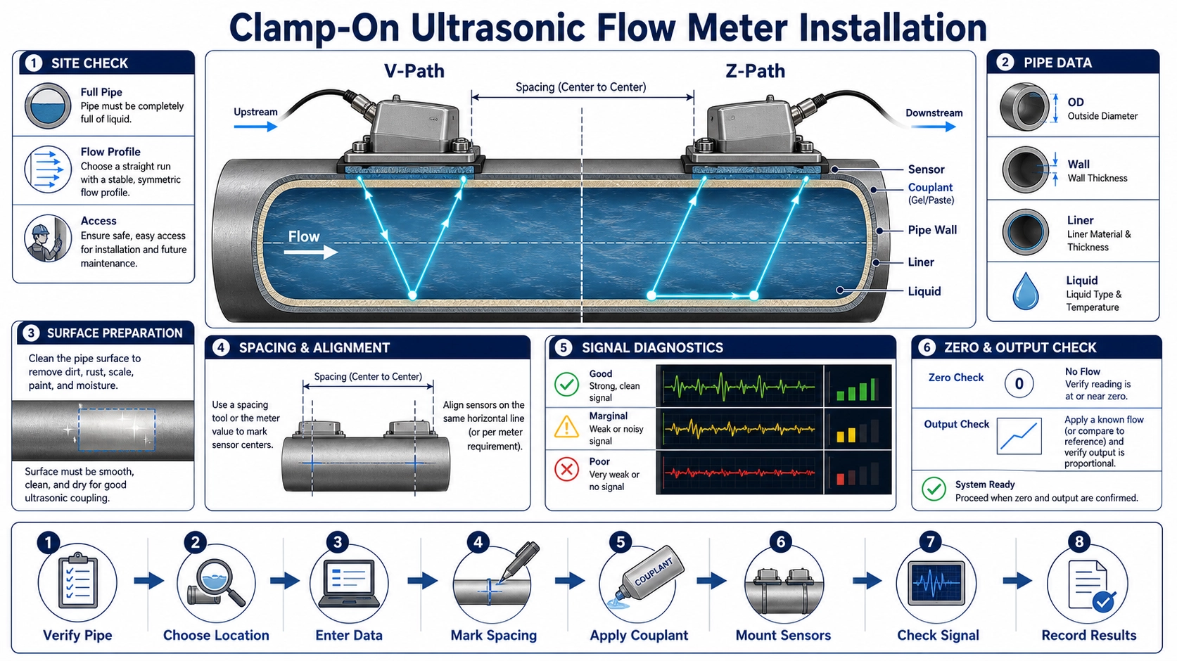
Installation is a measurement procedure, not only a mounting task
A clamp-on ultrasonic flow meter can be attached without opening the pipe, but a mechanically secure installation can still produce a wrong flow result. The instrument calculates through pipe dimensions, acoustic path, transit times, and configured units. An error in wall thickness, liner data, transducer arrangement, flow direction, or output scaling can survive a neat-looking installation.
This procedure covers transit-time clamp-on meters used on liquid-filled closed pipes. It is suitable as a commissioning framework, not as a replacement for the manual of the selected instrument, the site safety procedure, or a project-specific metering specification. Transducer spacing, supported pipe ranges, diagnostic limits, cable rules, and straight-run requirements must come from the actual product and approved project documents.
1. Freeze the measurement and safety basis
Before touching the pipe, identify why the point is being measured and what decision will be made from it. A temporary trend for troubleshooting, a pump performance check, a thermal energy calculation, and a permanent process totalizer have different evidence and output requirements. Record the expected flow direction, normal operating range, possible reverse flow, liquid state, pipe pressure and temperature, and whether the process can change during commissioning.
Complete the required permit, access, working-at-height, hot-surface, electrical, and hazardous-area controls. External installation removes the need to penetrate the pipe; it does not remove hazards around operating equipment. Confirm that surface preparation will not damage a pressure boundary or a protective system. If corrosion is suspected, obtain approval before removing scale or coating.
2. Qualify the proposed location
Walk the upstream and downstream piping rather than judging only the visible metre around the sensors. Note elbows in one or two planes, control valves, check valves, pumps, tees, reducers, heat exchangers, and injection points. These elements can distort the velocity profile or introduce gas. Select the best location allowed by the product manual and the project procedure. Avoid inventing a universal number of pipe diameters; required lengths depend on the disturbance, meter design, path arrangement, and acceptance objective.
- Choose a section that remains completely full over the operating range.
- Avoid the top of a horizontal pipe where gas may collect; follow the permitted transducer orientation for the instrument.
- Avoid low points that accumulate sediment if solids are present.
- Keep away from severe vibration, active welds, branches, and areas with rapidly changing wall thickness.
- Provide enough access to measure, align, clamp, inspect, and later service both transducers.
- Protect cables from hot surfaces, sharp edges, moving equipment, water ingress, and electrical interference.
3. Establish the real pipe geometry
Confirm the pipe identity against drawings, but measure the outside diameter at the proposed location when practical. Do not infer outside diameter from nominal size where multiple standards or schedules are possible. Obtain wall thickness from reliable documentation or a suitable thickness measurement. Identify any internal liner and its thickness. Record pipe material, surface coating, and condition.
These values determine refraction through the pipe wall and the calculated acoustic path. A wrong liner entry can be as important as a wrong wall thickness. If the pipe is badly corroded or deposits are suspected, the acoustic and hydraulic geometry may differ from the drawing. State the uncertainty instead of adjusting an input merely to force agreement with another indicator.
4. Select the transducer set and path arrangement
Use the instrument’s approved transducer type for the measured outside diameter, wall, liquid, and temperature. Enter the pipe and liquid data, then let the exact meter calculate the required spacing. Do not copy a spacing value from another pipe or model. The displayed spacing may refer to sensor faces, index marks, inner edges, or another datum; confirm the physical reference in the manual.
| Arrangement | Acoustic path | Where it is often useful | Installation risk to control |
|---|---|---|---|
| V method | The signal crosses the liquid, reflects from the opposite wall, and returns to the second transducer on the same side | Where signal level and pipe geometry support the longer path and same-side access is preferred | Incorrect spacing or pipe data moves the reflection point and weakens the received signal |
| Z method | The transducers are on opposite sides and the signal crosses the liquid once | Where attenuation makes a shorter path necessary or the manual recommends it | Angular and axial alignment across the pipe must be transferred accurately |
| Other supported methods | Multiple reflections or a dedicated fixture, depending on the instrument | Special pipe sizes, small tubes, or application-specific fixtures | Use only arrangements explicitly supported by the meter and transducer assembly |
V is not automatically “better” for small pipes and Z is not automatically “better” for large pipes. Frequency, attenuation, wall construction, available space, liquid condition, and transmitter capability all matter. Treat the meter’s diagnostic response during setup as evidence, not as permission to ignore its approved range.
5. Prepare, mark, couple, and clamp
- Mark a common axial reference and the calculated spacing datum before applying couplant.
- Remove loose paint, rust, scale, dirt, and high spots over the contact area without thinning the pipe or damaging an approved coating beyond the authorized area.
- Clean and dry the transducer face and pipe. Inspect the cable, connector, and contact surface.
- Apply the specified couplant as a continuous layer that excludes air. More couplant does not compensate for a rocking transducer or a rough surface.
- Seat each transducer in the indicated direction. Maintain the calculated spacing and a common centreline for same-side mounting.
- Tighten the straps or fixture evenly. Excess force can move the sensor, squeeze out couplant, or damage a small tube.
- Recheck spacing and alignment after tightening, then record the final dimension and photograph the installation.
6. Configure before judging the signal
Verify engineering units, outside diameter, wall, liner, pipe material, liquid, transducer type, arrangement, spacing datum, and flow direction. Check that the upstream and downstream transducer cables are connected to the correct channels. Do not swap cables simply to make the sign positive; correct the physical or configured direction and document it.
Review the diagnostics provided by the instrument: received signal, signal quality or correlation, transit times, time ratio, gain, and error flags. Names and acceptable ranges differ by model, so use the manual’s criteria. A high displayed signal alone is not proof of a correct installation. Look for stability over time and consistency with the entered sound path. Save or photograph the diagnostic page at normal operation.
7. Prove the reading under controlled process states
Zero check
Only perform a static zero when the procedure can establish true zero flow. A closed valve does not guarantee zero if bypasses, convection, leakage, or process recirculation remain. If true zero cannot be established, do not force the display to zero; document the condition and use the instrument’s approved alternative. Never use zero adjustment to hide an installation offset that changes with flow.
Direction and response
Start or change flow under authorized process control. Confirm that the sign follows the known direction and that the reading changes plausibly. Observe the diagnostics during low, normal, and, where available, higher flow states. Sudden signal loss only at one operating condition can indicate bubbles, profile changes, vibration, or a marginal acoustic path.
Independent comparison
Compare against a traceable reference, a calibrated process meter, a tank-volume/time test, a weigh system, or a documented mass/energy balance appropriate to the project. Account for synchronization, density conversion, accumulation, valve changes, and process storage. Agreement at one point does not validate the full range. Record the reference identity, status, time window, process condition, raw values, calculation, and acceptance criterion.
8. Commission outputs and totalization separately
A correct local display can still produce a wrong control-system value. Inject or observe at least two suitable operating points and verify analog zero and span, pulse weight and polarity, RS485 address and format, engineering units, decimal position, sign convention, totalizer behavior, loss-of-signal state, and alarm mapping. Confirm that a receiving system does not apply a second scaling or density conversion.
For energy calculations, verify that flow timing aligns with the temperature inputs and that supply and return sensors are assigned correctly. The dedicated ultrasonic heat meter working principle and selection guide explains why flow and temperature channels must be treated as one measuring system.
Commissioning record
- Asset and measurement purpose, date, operator, instrument and transducer identification.
- Pipe outside diameter, wall, liner, materials, condition, liquid, temperature, and process state.
- Upstream/downstream layout, transducer arrangement, spacing, orientation, surface preparation, and couplant.
- All configuration values, firmware or setup file where relevant, and output scaling.
- Diagnostic values and photographs after final tightening.
- Zero evidence, flow-direction check, comparison data, calculations, deviations, and acceptance decision.
- Maintenance requirement, including inspection of straps, cables, weather protection, and couplant where applicable.
If the diagnostic values or comparison fail, preserve the original evidence and follow the clamp-on flow meter troubleshooting sequence. Repeatedly changing inputs until the flow “looks right” destroys the information needed to identify the cause.
FAQ
How do I calculate transducer spacing?
Enter verified pipe, liner, liquid, transducer, and arrangement data into the selected instrument and use its calculated spacing and stated physical datum. A generic formula cannot capture every meter’s refraction model, delay, and fixture reference.
Should I always use V mounting first?
No. Use the arrangement approved for the pipe, transducers, liquid, and signal conditions. V offers same-side access and a longer path; Z offers a shorter crossing but requires accurate opposite-side alignment.
Can I zero the meter while the pump is stopped?
Only if the approved procedure establishes that liquid velocity is truly zero. Leakage, bypasses, thermal convection, and recirculation can remain after a pump stops.
Why does the PLC disagree with the local display?
Check units, output range, pulse weight, sign, byte or register format, totalizer handling, and any second scaling in the PLC. Test the signal chain independently from the acoustic measurement.
References and project support
ISO 12242:2012 provides the measurement framework for ultrasonic transit-time liquid meters in closed conduits. Use the edition and requirements specified by the project. For equipment selection before installation, see the handheld, portable, and fixed clamp-on flow meter comparison.
For installation review by Deep Minds Ultrasonic, send the meter and transducer model, pipe and liner dimensions, liquid and temperature, piping sketch, site photographs, configured spacing, diagnostic screens, required outputs, and acceptance method. These records make it possible to review the acoustic path and signal chain without guessing from the displayed flow alone.