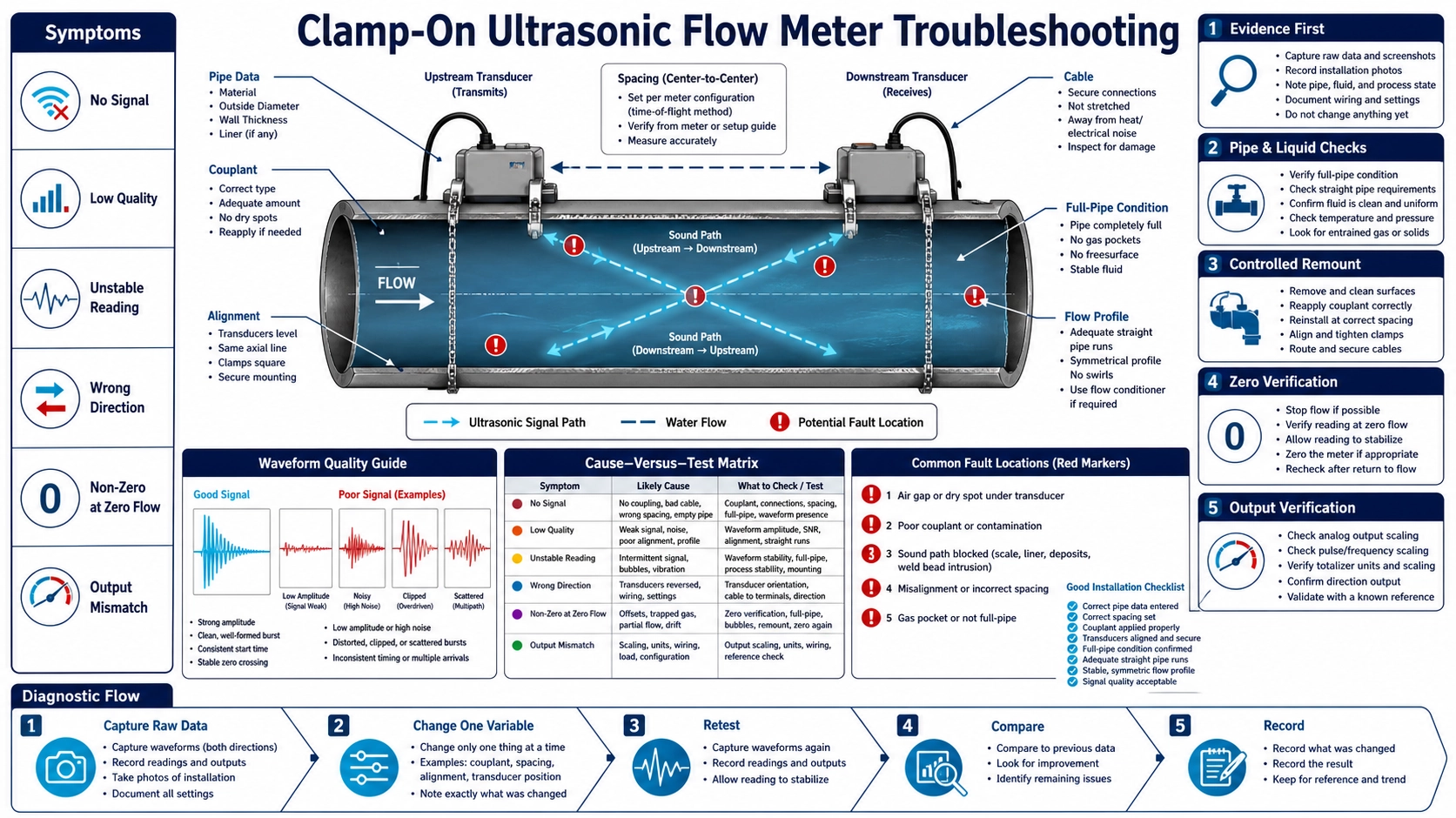
Preserve the evidence before changing the setup
A clamp-on ultrasonic flow meter fault can originate in the instrument, transducers, cables, entered pipe data, coupling, mounting geometry, pipe condition, liquid, flow profile, power, or output mapping. Several causes produce the same visible symptom. Moving the sensors and changing five parameters at once may restore a number, but it removes the evidence needed to know which cause mattered.
Begin by saving the configuration and recording the displayed flow, sign, totalizer, received signal, quality or correlation indicator, upstream and downstream transit times, time ratio, gain, sound velocity, error code, process state, and time. Different manufacturers use “Q,” signal quality, correlation, or confidence differently. Do not apply a threshold from another model; interpret each diagnostic using the manual for the installed instrument.
Build a fault record
- Instrument, firmware, transducer type, cable identity, power source, and output configuration.
- Pipe outside diameter, wall, liner, material, surface condition, and entered values.
- Liquid, temperature, pressure, solids or gas, full-pipe status, and known process changes.
- Arrangement, calculated and measured spacing, axial alignment, orientation, couplant, and mounting date.
- Upstream and downstream disturbances with distances and photographs.
- Raw diagnostic screens during the fault and, if available, during known good operation.
Trend the symptom if it is intermittent. Record whether it follows flow rate, pump operation, temperature, valve position, rain, vibration, a production recipe, or a particular time. Correlation is not proof, but it determines which controlled test should be run first.
Symptom-to-test map
| Observed symptom | First evidence to inspect | Controlled test | Do not assume |
|---|---|---|---|
| No received signal | Cable/channel, transducer selection, pipe inputs, gain/error flags | Electrical continuity and approved remount on a verified sound area | That the transmitter has failed |
| Low Q or poor correlation | Signal waveform or indicator stability, spacing, coupling, liquid condition | Renew one coupling interface or change only the approved path arrangement | That more gain makes the measurement valid |
| Unstable flow | Raw transit times, signal, process state, pump/valve events | Compare diagnostics at controlled steady process states | That the displayed damping should simply be increased |
| Stable but biased reading | Pipe geometry, liner, units, spacing datum, reference method | Independent dimension check and synchronized comparison | That a stable value is accurate |
| Non-zero reading at shutdown | Actual valve and bypass state, raw velocity, zero configuration | Establish true static conditions or document why this is impossible | That pump-off means zero liquid velocity |
| PLC differs from local display | Units, analog scaling, pulse weight, register format, sign | Test the output chain separately at known values | That the acoustic measurement is at fault |
No signal: separate the electrical path from the acoustic path
Check power, connectors, cable damage, channel assignment, and transducer identity before disturbing the pipe mounting. Use only continuity or electrical tests permitted by the manufacturer; an inappropriate meter or test voltage can damage or mischaracterize a piezoelectric device. If the electronics recognizes the transducers but receives no acoustic energy, verify the selected transducer set, entered pipe data, liner, liquid, arrangement, and spacing reference.
Inspect the contact zone. Loose scale, thick multilayer coating, a weld, a local wall defect, an air gap in couplant, or a transducer that rocks under the strap can block transmission. Mark the original positions before removal. Clean and recouple one transducer at a time, then compare the raw diagnostic. If moving to another approved position restores the signal, the conclusion is about that pipe area or flow location, not proof that the original electronics was defective.
If both channels fail after a wiring or configuration change, return to the last verified configuration. If one transducer or cable fails when swapped through an approved A/B test and the fault follows that component, isolate it for bench evaluation. Do not swap unapproved transducer types just because their connectors fit.
Low quality value: improve confidence, not only amplitude
A quality or correlation value usually reflects how confidently the instrument can identify the received waveform; it is not necessarily the same as signal amplitude. High gain may make noise larger without producing a reliable transit-time estimate. Compare signal strength, quality, gain, transit-time stability, and error flags together.
- Reconfirm actual outside diameter, wall, liner, material, liquid, transducer type, and arrangement.
- Measure the physical spacing from the exact datum specified by the manual.
- Check that both sensors share the required axis and face direction; for Z mounting, verify opposite-side transfer.
- Renew couplant after cleaning the faces and pipe. Look for dry edges, voids, or uneven pressure.
- Observe whether the quality follows liquid temperature, aeration, solids, or a pump operating point.
- Use another mounting method only if it is approved for the meter and pipe, changing no unrelated parameter during the comparison.
A marginal signal on an empty or partly full pipe cannot be fixed by polishing the setup. Prove the hydraulic state. Gas pockets commonly form near the top of horizontal pipes, while sediment may affect the bottom. Select an orientation allowed by the instrument and compatible with the process.
Unstable flow: determine whether the time measurement or the process is moving
Compare the displayed flow with raw transit-time and signal diagnostics. If flow fluctuates while both acoustic times and quality remain stable, investigate scaling, damping, totalizer sampling, or the receiving system. If transit times and signal vary together, the acoustic path or liquid condition is changing. If the raw velocity is stable but the reference meter changes, synchronization or process storage may explain the disagreement.
Observe pump speed, cavitation indications, valve movement, batch transitions, entrained gas, temperature, and vibration. Temporarily increasing display damping can make a trend look smooth while leaving the underlying measurement intermittent. Set filtering only after identifying the natural process dynamics and the response time required by the application.
For a permanent meter, inspect whether straps have relaxed, couplant has aged, condensation has entered a connector, or a cable now shares a route with a noisy drive. For temporary campaigns, check accidental sensor movement and whether the pipe temperature changed beyond the couplant or transducer condition assumed at installation.
Stable but wrong: audit every conversion
A stable biased reading often points to a repeatable setup error. Independently verify outside diameter and wall thickness. Check whether the entered value is diameter or circumference, millimetres or inches, and whether liner thickness was omitted or counted twice. Confirm liquid sound-velocity selection and temperature. Recheck the spacing datum and transducer direction.
Then audit the comparison. Are both meters reporting actual or standard volume, mass or volume, instantaneous flow or an average? Are their clocks aligned? Is density applied once? Does the comparison interval include storage in a tank or branch flow between the meters? Calculate from raw totals over a defined period rather than comparing two moving displays by eye.
Repeat a controlled remove-and-reinstall test where the procedure permits. The spread between independent installations reveals sensitivity to positioning and surface preparation. Do not tune wall thickness, sound speed, or calibration factor solely to force agreement unless a documented calibration procedure authorizes that adjustment and preserves traceability.
Non-zero at shutdown: prove zero before adjusting zero
A stopped pump does not guarantee static liquid. Leaking isolation valves, bypasses, gravity flow, thermal convection, recirculation, and another connected pump can maintain velocity. Review the piping and valve state, not just the motor status. Trend long enough to see whether the sign and magnitude are stable or random.
Only execute a meter zero procedure under the conditions required by its manual and the project. Record the pre-zero reading, diagnostics, process isolation evidence, action, and post-zero result. If true zero cannot be created safely, preserve the existing calibration and use an approved alternative. A large or frequently changing zero correction indicates that the underlying installation or process should be investigated.
Local display correct, remote value wrong
Separate the acoustic subsystem from the signal subsystem. For analog output, verify live-zero, span, units, direction, and the receiving input range. Measure the loop using an approved method and compare current with the transmitter’s commanded value. For pulses, confirm pulse weight, frequency limit, polarity, and whether the receiver counts both edges. For RS485/Modbus, check address, baud rate, parity, register, data type, byte order, scaling, and signed values.
Compare instantaneous values and totalizers separately. A PLC may apply an old engineering range after the transmitter was reconfigured, or convert litres to cubic metres twice. Document the test at more than one point so that offset and span errors can be distinguished.
When replacement is justified
Replace or repair a component when a controlled test makes the fault follow that component, it fails an approved bench check, physical damage is visible, or the manufacturer identifies an internal fault code. If a complete replacement produces the same symptom at the same site, return to pipe data, mounting, liquid, flow profile, power, and communication. A new transmitter cannot correct a non-full pipe or the wrong liner thickness.
Before changing the selected configuration, revisit the clamp-on flow meter selection guide. For a complete controlled reinstallation, use the installation and commissioning procedure. The BBUFM-F fixed clamp-on ultrasonic liquid flow meter should be evaluated against the recovered fault evidence.
FAQ
What is a good Q value?
There is no cross-manufacturer universal value. Use the range and meaning defined for the exact instrument, and evaluate it with signal level, gain, transit-time stability, and error status.
Will adding more couplant fix a weak signal?
Only if poor contact is the cause. Couplant cannot correct wrong pipe data, unsuitable transducers, a non-full pipe, severe attenuation, misalignment, or a damaged cable. Apply the specified material in a continuous layer on prepared surfaces.
Why does the meter work at low flow but fail at high flow?
The operating change may introduce bubbles, cavitation, vibration, or a different velocity profile, or push signal processing outside a stable condition. Trend raw diagnostics and process variables across the transition.
Can damping be increased to stop unstable readings?
Damping can match a valid noisy process signal to the required response time, but it should not hide intermittent acoustic reception. Identify the cause before changing filtering.
Reference and support evidence
ISO 12242:2012 is the relevant international measurement framework for ultrasonic transit-time liquid meters in closed conduits. Apply the project-specified edition and the instrument manufacturer’s diagnostic instructions.
For technical review by Deep Minds Ultrasonic, send the saved configuration, raw diagnostic screens, pipe and liner data, liquid and temperature, mounting photographs, process trend, output settings, reference comparison, and the result of each controlled test. A chronological fault record is more useful than a final screenshot taken after multiple unrecorded adjustments.