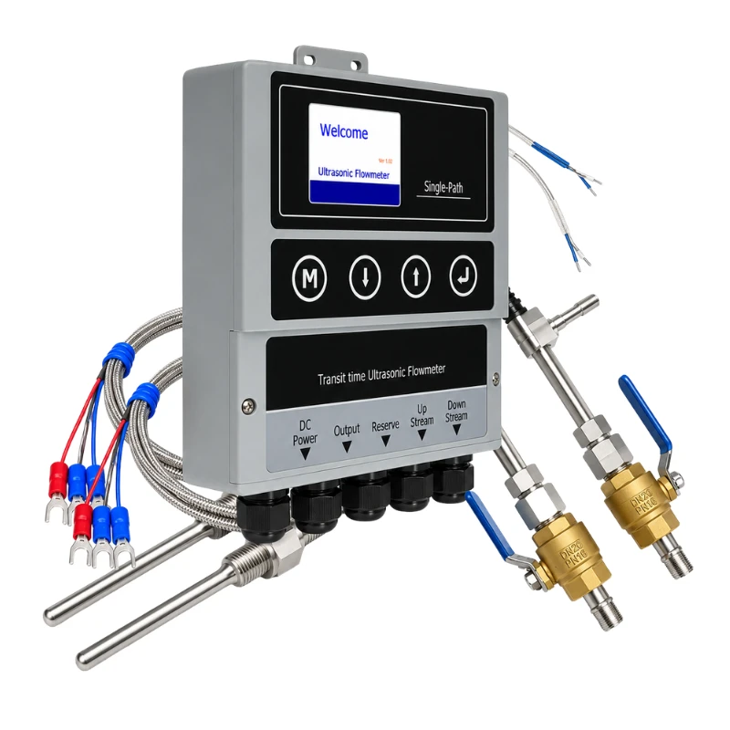
Product Overview
BBUEM-F is a fixed ultrasonic heating and cooling energy meter for chilled-water, hot-water, and HVAC energy-monitoring systems. It combines ultrasonic flow measurement with paired temperature measurement to calculate thermal energy from flow rate and supply/return temperature difference.
Standard and High-Accuracy configurations are available. Both support clamp-on flow transducers and clamp-on temperature sensors as standard, with wetted flow or temperature sensors available for applications that require direct-contact measurement.
Key Features
- Measures flow, temperature difference, and heating/cooling energy
- Clamp-on installation without cutting the pipe in the standard configuration
- Standard and High-Accuracy performance configurations
- Pipe-size coverage up to 5000 mm
- Matched temperature sensors with 0.02 °C matching error
- 4–20 mA, pulse/OCT, and relay outputs
- RS485 communication with Modbus protocol
- Optional wetted flow and temperature sensors
Typical Applications
- Central air-conditioning systems
- Chilled-water and hot-water networks
- Building heating and cooling energy metering
- District and plant utility monitoring
- Industrial cooling and heat-exchange systems
- Energy-management and sub-metering projects
Measurement Principle
Thermal energy is calculated from the measured liquid flow and the temperature difference between the supply and return sides of the system. The flow meter uses the ultrasonic transit-time principle, while a matched temperature-sensor pair provides the temperature-difference input.
Technical Specifications
| Parameter | Standard | High Accuracy |
|---|---|---|
| Velocity range | 0 to ±12 m/s | 0 to ±12 m/s |
| Flow accuracy | ±1.0% of measured value | ±0.5% of measured value |
| Heating/cooling energy accuracy | ±2.0% | ±2.0% |
| Temperature matching error | 0.02 °C | |
| Pipe size | 25 to 2000 mm | 25 to 5000 mm |
| Temperature measurement range | 2 to 105 °C | |
| Analog output | 4–20 mA, maximum load 750 Ω | |
| Pulse output | 0–9999 Hz, OCT | |
| Relay output | SPST, max. 1 Hz | |
| Communication | RS485, Modbus protocol | |
| Power supply | 24–36 VDC | |
| Display | 2.2-inch TFT LCD, 320 × 240 | 2.8-inch TFT LCD, 320 × 240 |
| Transmitter operating temperature | -40 to 60 °C | |
| Standard flow-transducer temperature | -40 to 80 °C | |
| Humidity | Up to 95% RH, non-condensing | |
| Transmitter enclosure | PC plastic enclosure | Die-cast aluminum |
Sensor Options
| Measurement | Standard | Optional |
|---|---|---|
| Flow | Clamp-on ultrasonic transducer | Wetted ultrasonic transducer |
| Temperature | Clamp-on temperature sensor | Wetted temperature sensor |
Configuration Options
| Configuration | Application and Features |
|---|---|
| Standard | ±1.0% flow accuracy, 25–2000 mm pipe range, PC plastic transmitter enclosure |
| High Accuracy | ±0.5% flow accuracy, 25–5000 mm pipe range, die-cast aluminum transmitter enclosure |
Selection Information
- Pipe outside diameter, wall thickness, and material
- Heating or cooling medium
- Supply and return temperature range
- Expected flow range
- Required accuracy level
- Clamp-on or wetted sensor requirement
- Required output and communication interface