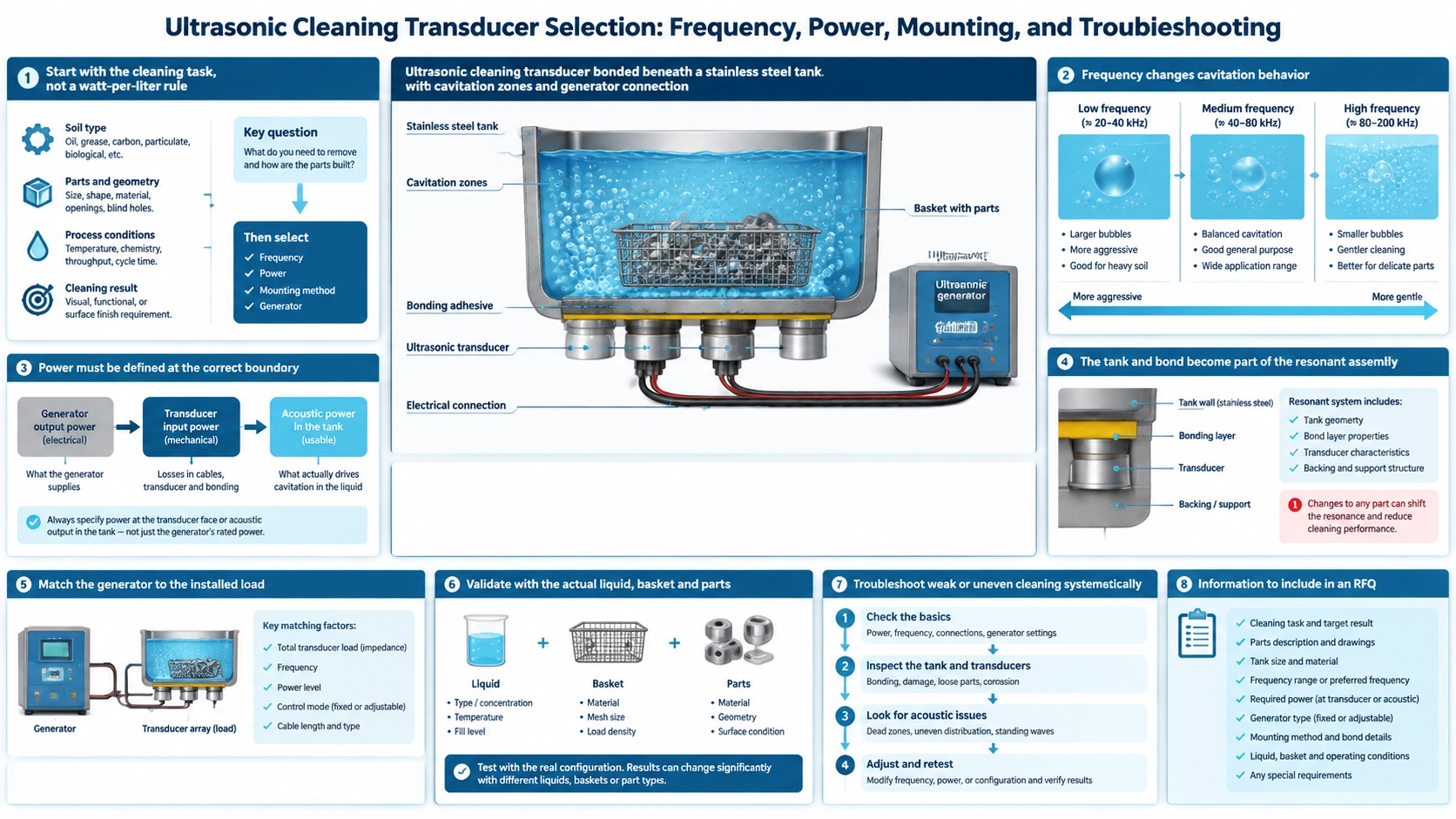
Start with the cleaning task, not a watt-per-liter rule
An ultrasonic cleaning transducer converts the generator output into vibration of the tank or immersible plate. That vibration creates alternating pressure in the liquid, producing cavitation that loosens contamination. The useful result depends on the entire chain: generator, transducer, bond, tank, liquid, temperature, basket, load and cleaning cycle.
Watts per liter is useful for an early estimate, but it cannot specify a system alone. Two tanks with the same volume may have different wall thickness, shape, liquid depth, fixtures and part loading. Define the contaminant, substrate, required cleanliness, throughput and risk of surface damage before selecting hardware.
Frequency changes cavitation behavior
Lower frequencies generally produce larger, more energetic cavitation events and are commonly chosen for robust parts and heavy contamination. Higher frequencies produce finer cavitation and can be better for small features or delicate surfaces. Frequency does not guarantee a result: chemistry, temperature, dissolved gas, acoustic field and exposure time remain important.
A 40 kHz system is a common industrial starting point because it balances cleaning action, component size and audible behavior for many general applications. The BBCL-40KP100 40 kHz 100 W cleaning transducer is a component for this type of system; its rating is not a promise that one unit will clean a particular tank or part.
Power must be defined at the correct boundary
Generator electrical input, electrical power delivered to the transducer and acoustic power coupled into the liquid are not interchangeable values. Peak power and average power also describe different operating conditions. Confirm how the supplier defines the stated wattage, duty cycle and permissible drive voltage.
Size the installed transducer count from tank area, liquid volume, load, distribution and required cycle time. More nominal power can cause heating, erosion, standing-wave hot spots or overload without improving uniformity. A larger tank may need better spatial distribution rather than simply higher drive.
The tank and bond become part of the resonant assembly
A bonded transducer does not operate as a free component. Tank material, wall thickness, curvature, welds, adhesive thickness, clamping pressure and cure process all shift the response. The mounting surface must be flat, clean and prepared for the selected bonding system. Poor bond coverage creates heat and reduces acoustic transfer.
Place multiple transducers so their fields cover the working zone without concentrating stress near welds, drains or sharp changes in stiffness. The final placement should be validated with the real tank and liquid depth. Copying a layout from a tank of different geometry is risky even when the total volume is similar.
Match the generator to the installed load
The generator must accommodate the capacitance, resonance range and impedance of the complete installed group. Cable length, parallel connections and temperature alter the electrical load. Automatic frequency tracking can help follow operating shifts, but it cannot correct a detached bond, unsuitable tank or badly distributed field.
Before full-power operation, verify wiring, insulation, grounding and the generator’s supported transducer configuration. Increase drive under liquid load while observing current, frequency tracking, temperature and abnormal sound. Never assume an unloaded dry tank represents normal conditions.
Validate with the actual liquid, basket and parts
Degas fresh solution before judging performance. Dissolved gas absorbs acoustic energy and can make a healthy system appear weak. Record chemistry concentration, temperature, liquid depth and part loading because each changes cavitation. Keep parts off the tank bottom and prevent baskets from damping the active surfaces.
Use repeatable cleanliness criteria rather than relying only on visible agitation. Foil tests or field mapping can reveal distribution, but the acceptance test should use representative parts and contamination. Confirm both cleaning effectiveness and absence of pitting, coating damage or dimensional change.
Troubleshoot weak or uneven cleaning systematically
- Weak everywhere: check degassing, liquid level, generator output, tracking, wiring and excessive load.
- Weak in one zone: inspect transducer placement, bond integrity, tank damage and basket contact.
- Rapid heating: check off-resonance drive, poor bonding, excessive duty cycle, cooling and chemical temperature limits.
- Unstable sound or current: inspect loose connections, liquid-level changes, intermittent bonds and generator protection events.
- Good cavitation but poor cleaning: review chemistry, contaminant compatibility, time, temperature and part orientation.
Record impedance or current trends before disassembly. Replacing a transducer without identifying the system-level cause may damage the replacement in the same way.
Information to include in an RFQ
Provide tank dimensions, material and wall thickness; working liquid depth and chemistry; part material, contamination and load; required cycle time; available generator; supply voltage; continuous or intermittent duty; mounting method; ambient and liquid temperature; and acceptance test. State whether you need a bare transducer, a bonded assembly, an immersible pack or a complete generator-and-tank solution.
ASTM G131, Standard Practice for Cleaning of Materials and Components by Ultrasonic Techniques, provides a recognized framework for defining and controlling an ultrasonic cleaning process. Apply it together with tank-specific trials. For equipment development or repair, use the circuit-matching guide to check the installed electrical load, the transducer testing guide to establish a baseline, and the replacement guide before substituting a failed unit.
FAQ
Is 40 kHz suitable for every ultrasonic cleaning application?
No. It is widely used for general cleaning, but heavy contamination, very delicate parts or fine internal features may require another frequency or a multistage process.
Can I increase cleaning strength by adding more transducers?
Only after checking tank mechanics, generator capacity and field distribution. Additional transducers can create stress or hot spots if the system is not redesigned.
Why does a transducer run hot?
Possible causes include poor bonding, off-resonance operation, excessive voltage or duty, insufficient cooling, loose hardware and unsuitable electrical matching.
Should the system be tested without liquid?
Only at the limited conditions permitted by the manufacturer. Normal tuning and full-power validation should use the specified liquid load because dry operation changes the mechanical and electrical response.