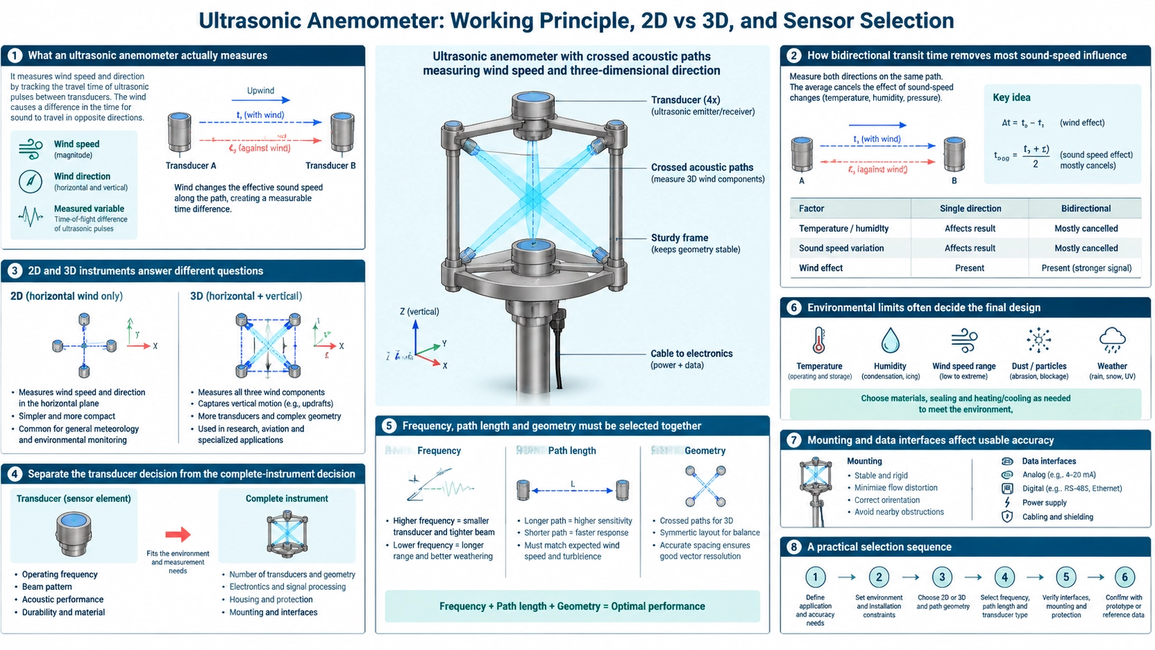
What an ultrasonic anemometer actually measures
An ultrasonic anemometer measures the effect of moving air on the travel time of an acoustic pulse. Transducers face each other across one or more known paths. A pulse traveling with the wind arrives sooner than a pulse traveling against it. The difference between the two transit times yields the wind component along that path.
Two crossed horizontal paths can resolve horizontal wind speed and direction. A three-dimensional instrument adds inclined or vertical paths so it can also resolve vertical velocity. Because there are no cups, vanes or propellers, the measurement does not depend on the starting torque of a moving rotor. That is useful for low-speed response, rapid sampling and installations where mechanical wear is undesirable.
How bidirectional transit time removes most sound-speed influence
For a path length L, the downstream and upstream pulse times depend on both the speed of sound c and the wind component v. Measuring in both directions allows the electronics to separate the directional airflow term from the common sound-speed term. Temperature still matters to signal timing, acoustic attenuation and diagnostics, but it does not need to be converted directly into wind speed as it would in a one-way measurement.
The useful result depends on more than the timing formula. The instrument must identify the pulse consistently, control ringing, reject false arrivals and compensate fixed channel delays. Path length, transducer bandwidth, drive amplitude, gain and sampling rate therefore form one measurement system.
2D and 3D instruments answer different questions
A 2D ultrasonic wind sensor reports the horizontal vector, usually as speed plus compass direction or as orthogonal X and Y components. It suits weather stations, cranes, ports, tunnels, building controls and equipment protection when vertical airflow is not a required output.
A 3D ultrasonic anemometer also measures the vertical component. It is used for turbulence, eddy covariance, boundary-layer research and flow studies around structures. The extra axis changes the mechanical geometry, channel count, calibration work and data processing. Choosing 3D only because it appears more capable can add cost without improving a horizontal-wind application.
Separate the transducer decision from the complete-instrument decision
An ultrasonic wind transducer is an acoustic component. A complete anemometer also includes the path geometry, timing electronics, temperature sensing, algorithms, housing, mounting, communication interface and calibration. OEM teams developing their own electronics may need matched transducer pairs such as the BBFM-V200K-B ultrasonic wind transducer. Users who need a ready measurement output should evaluate a complete instrument such as the BBUAM-3D three-dimensional ultrasonic anemometer.
Define the supply boundary in the RFQ. A transducer specification alone does not establish system accuracy, wind range or environmental performance.
Frequency, path length and geometry must be selected together
Higher acoustic frequency can support compact paths and precise timing, but atmospheric attenuation, rain contamination and alignment sensitivity may increase. Lower frequency can offer more propagation margin, but normally requires larger components and may constrain time resolution. The best frequency is therefore tied to the intended path length, aperture, pulse shape and signal-processing method.
Mechanical supports create flow shadow and turbulence. A compact head is not automatically better if its arms disturb the acoustic paths. For OEM designs, compare candidates such as the BBFM-V40K and higher-frequency BBFM-V series by installed path performance, not nominal frequency alone.
Environmental limits often decide the final design
Rain, fog, dust, salt spray, ice and condensation can weaken or distort the received pulse. Temperature range affects materials, electronics and acoustic velocity. Strong vibration can move the path geometry, while nearby structures can alter the actual airflow before it reaches the sensor.
Specify enclosure protection, corrosion resistance, heater requirements, drainage, cable sealing and lightning or surge protection where applicable. If the instrument will be used offshore, on a moving platform or in freezing weather, validate those conditions explicitly rather than relying on a general outdoor rating.
Mounting and data interfaces affect usable accuracy
Install the head away from walls, masts, exhausts and rotating equipment that distort the flow. Align the reference axis to the required coordinate system and record any mounting offset. A 3D instrument also needs a defined tilt convention because a small angular error mixes horizontal velocity into the vertical channel.
Confirm update rate, averaging interval, digital protocol, analog outputs, time synchronization and diagnostic flags. A fast internal sampling rate does not guarantee a fast or low-latency external output. For control systems, define the acceptable behavior during blocked-path or low-signal conditions.
A practical selection sequence
- Define whether horizontal wind or the complete 3D vector is required.
- Set the expected speed range, response time and averaging method.
- Describe temperature, precipitation, icing, contamination and vibration.
- Choose a complete instrument or an OEM transducer-level solution.
- Confirm mounting clearance, orientation, outputs, power and calibration evidence.
- Test the installed assembly against representative wind and environmental conditions.
This sequence prevents a high-volume keyword such as “ultrasonic wind sensor” from being treated as a complete engineering specification.
The WMO Guide to Instruments and Methods of Observation provides the wider reference for meteorological instrument exposure, siting and measurement practice. For component-level design, use the ultrasonic transducer testing guide to define acceptance data, the beam-angle guide to review path geometry, and the air- versus liquid-coupled comparison to avoid applying liquid-transducer assumptions to wind sensing.
FAQ
Does an ultrasonic anemometer need a wind vane?
No. Crossed acoustic paths resolve the vector components electronically, so direction can be calculated without a mechanical vane.
Is a 3D ultrasonic anemometer always more accurate than a 2D model?
No. It measures an additional component, but usable accuracy still depends on geometry, calibration, mounting and the application. A well-installed 2D sensor is the correct choice for many horizontal-wind tasks.
Can wind transducers with the same frequency be interchanged?
Not automatically. Capacitance, bandwidth, sensitivity, beam pattern, housing, matching and environmental sealing must also fit the electronics and mechanical path.
What should be tested before deployment?
Verify zero behavior, directional response, speed response, path diagnostics, output timing and recovery from rain, blockage or low signal under conditions representative of the installation.