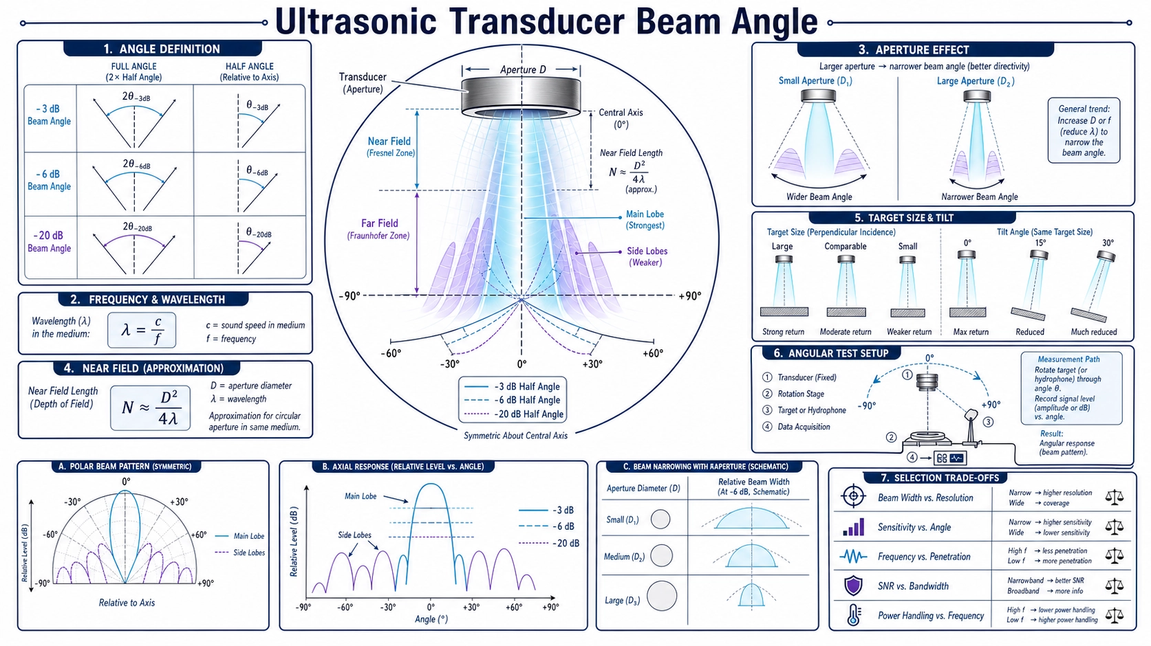
A beam angle needs a definition before it needs a number
“Beam angle” is often treated as one fixed property, but a transducer does not project a cone with a hard edge. Acoustic pressure varies continuously with direction and distance. A catalogue angle may be measured between -3 dB points, -6 dB points, another threshold, or first nulls; it may describe transmit pressure, receive sensitivity, or a combined pulse-echo response. Those definitions produce different numbers for the same device.
Before comparing two ultrasonic transducers, ask for the level criterion, full angle or half angle, measurement plane, distance, medium, frequency, mounting, target or receiver, drive and signal processing. Without those conditions, “15 degrees” and “20 degrees” may not represent a real performance difference.
The beam is a spatial response
An active aperture contains many vibrating points. Their waves combine constructively and destructively in space. On axis, contributions may reinforce. Off axis, phase differences reduce the sum and can create nulls and side lobes. The resulting field depends on wavelength relative to the effective aperture and on the amplitude and phase distribution across that aperture.
A simple uniformly vibrating circular piston is useful for understanding trends, but a commercial transducer also includes a piezoelectric element, matching layers, backing, housing, protective face, adhesive, curvature, damping, and mounting boundary. These can change the effective aperture and introduce non-axisymmetric behavior. Use the piston model as an estimate, then measure the completed assembly.
Do not mix beam-angle conventions
| Convention | Meaning | Common use | Comparison risk |
|---|---|---|---|
| -3 dB points | Response falls to a specified half-power-related level under the adopted amplitude convention | Bandwidth-style reporting and some sensor datasheets | The quantity may be pressure, voltage, intensity, or combined response |
| -6 dB points | Response falls to one-half amplitude when expressed as 20 log amplitude ratio | Many ultrasonic beam plots and NDT conventions | Not interchangeable with -3 dB or a detection threshold |
| First-null angle | Direction of the first theoretical or measured minimum beside the main lobe | Aperture theory and beam-spread estimates | Much wider than a half-power beam and sensitive to real aperture behavior |
| Detection angle | Angular region in which a specified target is detected at a stated threshold | Object-detection applications | Includes target size, reflectivity, range, gain, threshold, and processing |
Always state whether the reported value is the full angle between two symmetric points or the half angle from axis to one point. A full -6 dB angle of 20 degrees and a -6 dB half angle of 20 degrees differ by a factor of two.
Frequency, wavelength, and aperture set the basic trend
Wavelength is the sound speed in the medium divided by frequency. For the same medium and aperture, increasing frequency shortens wavelength and generally narrows the main lobe. Increasing effective aperture at the same frequency also generally narrows it. Conversely, a small aperture relative to wavelength produces a wider beam.
That trend is not a complete selection rule. Higher frequency may experience greater attenuation in the medium or through protective structures, while a larger aperture increases package size and can extend the near-field region. The transducer’s actual operating frequency may shift with acoustic loading and mounting. Temperature and gas composition change sound speed and therefore wavelength.
Analytical expressions often contain a coefficient multiplied by wavelength divided by aperture. The coefficient changes with the chosen beam criterion and aperture model. Using a first-null coefficient to predict a -6 dB angle is a definition error, not merely an approximation. For rectangular apertures, beam widths differ in the two principal planes.
Near field: why a neat cone is misleading close to the face
Close to the transducer, waves from different parts of the aperture interfere through rapidly changing paths. This Fresnel or near-field region can contain local maxima and minima; pressure does not simply decrease smoothly with distance. For a simple circular piston, a commonly used near-field estimate scales with aperture diameter squared divided by wavelength. The exact boundary and measured pattern depend on the real aperture and definition.
In the far field, the angular pattern becomes more stable and the main lobe spreads. A target placed inside or near the transition can produce strong changes from a small movement. Therefore a beam angle measured at one short distance should not automatically be projected to long range. A distance sensor also has a practical blind region driven by ring-down and receiver recovery, which is different from the acoustic near field even though the two regions may overlap.
Side lobes create off-axis detections
Destructive interference creates nulls, but constructive interference can return farther off axis as side lobes. A side lobe may detect a tank wall, bracket, pipe, curb, or machine frame outside the main lobe. Increasing a threshold can suppress some weak side-lobe echoes, but it can also remove the intended weak target. Mechanical baffles or acoustic horns may reshape the field while adding resonances or environmental sensitivity.
A narrow headline beam angle does not guarantee low side lobes. Ask for an angular response plot over a wide enough range and at the relevant frequency. For object detection, test the complete housing and nearby structure because a bezel or recess can reflect and diffract sound.
The target changes the apparent detection zone
A large flat plate normal to the axis returns more energy than a small, soft, tilted, curved, porous, or irregular object. A target can be inside the main lobe yet remain undetected, or it can be outside the nominal angle and still create a specular or side-lobe echo. Range, atmospheric attenuation, turbulence, temperature gradients, surface motion, gain, time-varying gain, and threshold all influence the observed zone.
For level measurement, a calm liquid surface differs from foam, an angled granular pile, or a surface with internal structures nearby. For parking detection, a wall differs from a pole or curb. For a through-beam system, the relevant quantity may be coupling between a transmitter and receiver rather than echo from a target. The test target should represent the application decision.
How to measure angular response
- Define whether the test is transmit, receive, through-transmission, or pulse-echo and specify the response quantity.
- Choose a medium and temperature, then document sound speed or the data used to determine it.
- Mount the transducer in its final or representative housing on a rigid rotation fixture with the acoustic center referenced to the rotation axis.
- Use a calibrated receiver or a defined target at a controlled distance. Select a distance and time gate that separate the intended arrival from fixture and room reflections.
- Fix frequency, waveform, terminal voltage, cycles, receive gain, bandwidth, filtering, gate, and threshold.
- Scan angle with a stated step in at least the required principal planes. Repeat the on-axis point during the run to detect drift.
- Normalize only after preserving the absolute or raw response. Report the criterion, full or half angle, nulls, side lobes, distance, and uncertainty.
The ultrasonic transducer testing guide provides the broader fixture, waveform, repeatability, and acceptance framework. NDE-Ed’s material on radiated fields and transducer beam spread illustrates the aperture, near-field, and divergence relationships. Apply its formulas only with their stated assumptions and definitions.
Select the beam from the scene, not from “narrow is better”
| Application need | Beam implication | Other condition to verify |
|---|---|---|
| Isolate a small target among nearby structures | A narrower main lobe and controlled side lobes may help | Target reflectivity, alignment tolerance, vibration, and aperture size |
| Cover a wide detection zone | A wider response may reduce pointing sensitivity | Multiple echoes, threshold logic, and false-target rejection |
| Long-range distance measurement | Directivity can concentrate energy | Attenuation, drive limits, receiver noise, target, and environmental gradients |
| Small tank opening or standpipe | Beam must clear the neck and internal fittings | Near field, ringing, condensation, nozzle geometry, and wall echoes |
| Paired through-beam sensing | Transmit and receive patterns must overlap with assembly tolerance | Fixture repeatability, cable delay, temperature, and mechanical shift |
For distance-product selection, combine beam data with the ultrasonic distance sensor range and frequency guide and the 14 kHz to 400 kHz distance transducer guide. For air measurements affected by temperature, also see the ultrasonic distance temperature compensation guide; for underwater work, see the underwater depth transducer frequency guide. Frequency, range, beam, blind zone, enclosure, output, and target must be selected as one system.
Information to request from a supplier
- Angular plots in the required planes, not only a single angle.
- Definition of response level, full or half angle, frequency, medium, temperature, distance, and mounting.
- Transmit, receive, or combined measurement method and target or reference receiver.
- Main-lobe width, first nulls, relevant side-lobe levels, sample variation, and tolerance.
- Effects of the final housing, protective face, horn, recess, cable, and mounting torque.
- Raw data or test report when the beam is a critical acceptance parameter.
FAQ
Does higher frequency always give a narrower beam?
For the same effective aperture and medium it generally narrows the main lobe, but the final assembly, modes, loading, attenuation, and operating frequency can change the result. Measure the completed design.
Is near field the same as blind zone?
No. Near field describes spatial interference close to an aperture. Blind zone is the minimum usable measurement region produced by ring-down, switching, receiver recovery, threshold, target, and geometry. They can overlap but are not identical.
Can a beam angle be calculated from frequency and diameter?
A model can estimate a specific criterion for an assumed aperture, but it cannot capture every housing, mode, matching layer, or side lobe. State the model and definition, then verify by measurement.
Why is a target detected outside the specified angle?
The specification may use another level criterion, while the real target may return through side lobes, diffraction, or nearby reflections. Gain and detection threshold also expand or contract the practical detection zone.
Define the required beam for engineering review
To review an application with Deep Minds Ultrasonic, send the medium, frequency range, target dimensions and material, minimum and maximum distance, allowed field of view, nearby structures, mounting aperture, housing, temperature, drive and receive settings, required beam criterion, test method, and quantity. A target scene and acceptance definition are more actionable than asking only for the “narrowest” transducer.