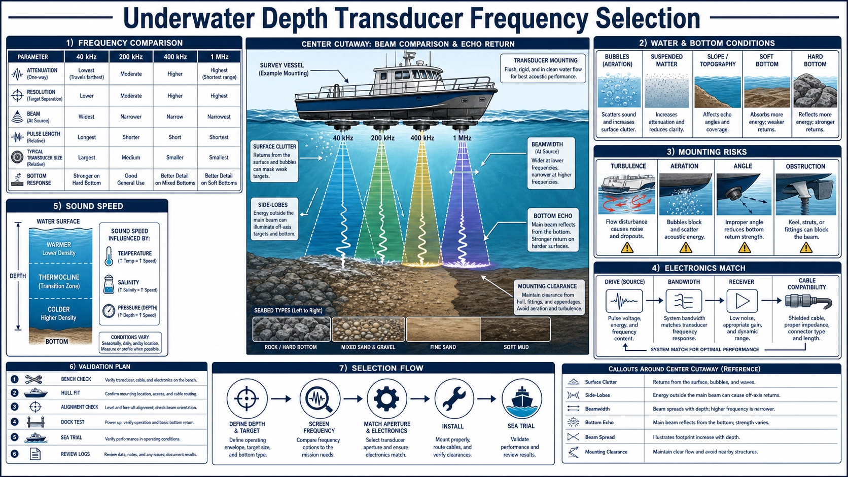
Frequency is a system trade-off, not a depth label
An underwater depth transducer sends acoustic energy toward the bottom and receives returned echoes. Frequency affects wavelength, attenuation, beam pattern, transducer size, pulse design, and the way different bottom materials appear, but it does not assign a guaranteed maximum depth by itself. The result also depends on transmit energy, pulse length, receiver noise, bandwidth, aperture, installation, vessel motion, water properties, bottom slope and reflectivity, bubbles, and signal processing.
A 40 kHz, 200 kHz, 400 kHz, 500 kHz, or 1 MHz product should therefore be selected from the complete sounding requirement. A low frequency may support a longer or more penetrating path under suitable conditions, while a high frequency can support a shorter wavelength and finer temporal or spatial detail. Neither statement replaces a link budget and field validation.
Translate the survey task into acoustic requirements
- Minimum and maximum water depth, including draft and transducer offset.
- Required vertical resolution, update rate, and confidence during motion.
- Fresh, brackish, or seawater; expected temperature, salinity, and pressure range.
- Bottom type: hard rock, sand, silt, vegetation, soft sediment, or layered material.
- Vessel speed, heave, pitch, roll, bubbles, wake, turbulence, and mounting location.
- Available aperture, beam requirement, hull or pole interface, cable route, connector, and sealing.
- Transmitter voltage and waveform, receiver bandwidth and noise, time-varying gain, and processing.
- Whether one bottom interface or differences between two frequency responses are required.
How frequency changes the design
| Frequency region | General tendency | Potential use | Condition that can reverse the advantage |
|---|---|---|---|
| Around 40 kHz | Longer wavelength, generally less absorption than much higher frequencies, larger resonant structures for similar design | Longer paths or soft-bottom response where penetration is useful | Wide beam from a small aperture, longer ring-down, coarse pulse, noise, or insufficient power |
| Around 200 kHz | Common compromise between compact size, beam control, detail, and practical depth sounding | General navigation, small craft, tanks, rivers, and moderate water paths | Air bubbles, poor mounting, weak bottom, or electronics not matched to the transducer |
| Around 400–500 kHz | Shorter wavelength and potential for narrower beam with the same aperture and shorter pulses | Shallow-water detail, compact geometry, or closer targets | Higher absorption and scattering can reduce usable path and margin |
| Around 1 MHz | Very short wavelength and potential for fine near-range resolution | Short-path profiling, level or interface work, and controlled shallow applications | Attenuation, bubbles, surface contamination, and limited transmit-receive recovery |
The table describes tendencies, not product depth ratings. A well-designed lower-power high-frequency system may outperform a poorly installed low-frequency system at a particular site. Conversely, high resolution in a tank does not imply performance in deep open water.
Wavelength, pulse length, and range resolution
Wavelength is sound speed divided by frequency. A shorter wavelength can interact with smaller features and permits a compact aperture to achieve a given directivity. Vertical separation of two echoes, however, also depends on the transmitted pulse duration and receiver bandwidth. A simple time-domain estimate relates two-way range extent to sound speed multiplied by pulse duration and divided by two. Long bursts carry more energy but occupy more distance and increase overlap between close interfaces.
Signal processing can improve detection and estimate arrival time, but it cannot recover information eliminated by a narrow bandwidth, excessive ring-down, saturation, or unresolved echoes without assumptions. Define resolution using a specified target, separation, signal-to-noise ratio, waveform, and algorithm. Do not equate operating wavelength directly with guaranteed depth resolution.
Beam width and the surveyed footprint
For a given effective aperture, shorter wavelength generally narrows the main lobe. A narrow beam reduces the bottom footprint and may separate nearby features or reduce averaging over a slope. It is also more sensitive to pitch, roll, misalignment, and a target leaving the beam. A wider beam covers more area but can return the first strong echo from one side of a sloping bottom rather than the point directly below.
Compare angular response at the actual frequency and mounting, including side lobes. The ultrasonic transducer beam-angle guide explains why -3 dB, -6 dB, first-null, and detection angles must not be mixed. For a dual-frequency housing, each frequency can have a different effective aperture and beam.
Bottom type and frequency-dependent echoes
A hard smooth bottom can produce a strong specular reflection, especially near normal incidence. A rough bottom scatters energy; a soft sediment layer may return from its upper boundary while lower frequency energy may interact differently with deeper or denser layers. Vegetation and suspended material add distributed echoes. The apparent “depth” can therefore depend on frequency, threshold, pulse, and bottom-detection algorithm.
Dual-frequency sounding is valuable when the application needs complementary responses rather than merely a backup number. The BBDM-40K200KR200M-UW 40/200 kHz dual-frequency transducer provides two acoustic frequencies in one product format. The system designer must define how the channels are timed, isolated, calibrated, and interpreted; two traces are not automatically two independent true depths.
Water properties and sound-speed correction
Depth equals one-half of the round-trip time multiplied by an appropriate path sound speed. In water, sound speed depends on temperature, salinity, and pressure. A fixed value may be adequate only within a bounded uncertainty and environment. Vertical sound-speed gradients can refract the acoustic path, especially over long ranges or in stratified water.
Specify whether a local temperature sensor, conductivity-temperature-depth data, a sound-velocity profiler, or a project-defined constant will be used. Record the transducer draft and reference datum. Compensation cannot correct a wrong bottom echo, vessel heave, mounting angle, or an unmeasured offset between the transducer face and the reported waterline or tank reference.
Mounting can dominate the frequency choice
The active face needs clear water and a stable view of the bottom. Avoid aerated flow, propeller wash, hull steps, intakes, outlets, turbulence, and locations that emerge or ventilate during motion. A fairing, pole, through-hull, or tank fitting changes mechanical boundary, flow, and acoustic window. Confirm that any hull material or window is explicitly included in the acoustic design; a transducer intended for direct immersion should not be assumed to transmit through an arbitrary structure.
Control face orientation, draft, sealing, cable bend, strain relief, galvanic compatibility, pressure exposure, impact risk, fouling, and service access. Cavitation, bubbles, marine growth, paint, and deposits reduce coupling. Do not coat the acoustic face unless the coating and thickness are approved.
Match the electronics to the transducer
Obtain impedance magnitude and phase across the operating band under representative acoustic loading. Define capacitance, resonance, bandwidth, maximum permitted drive, burst length, repetition rate, duty cycle, and temperature. The cable and connector add capacitance, loss, delay, and noise pickup. Long cables may require the receiver or matching network to be designed around the installed length.
On transmit, verify voltage at the transducer terminals and manage ringing. On receive, protect the front end, control recovery, gain and bandwidth, and prevent the transmit event from saturating the measurement window. The ultrasonic transducer testing guide gives a method for impedance, acoustic response, ring-down, and pair characterization.
Frequency selection workflow
- Define depth range, required resolution, update rate, bottom types, motion, and environmental envelope.
- Estimate two-way propagation loss, bottom return, noise, required margin, and the effect of bubbles and scattering.
- Choose candidate frequency regions and apertures, then estimate beam footprint and pulse-limited resolution using consistent definitions.
- Select the mechanical format, mounting, acoustic window, cable, and pressure/environmental construction.
- Match transmitter and receiver to measured loaded impedance and required waveform.
- Bench-test in a controlled water path, then test representative bottoms and ranges.
- Validate on the final platform with motion, bubbles, speed, temperature/salinity profiles, and independent depth references.
- Freeze detection settings, sound-speed handling, offsets, calibration, diagnostics, and acceptance limits.
Candidate products to evaluate
Deep Minds Ultrasonic offers underwater depth transducer formats including BBDM-40K-UW 40 kHz, BBDM-200K-UW 200 kHz, BBDM-400K-UW 400 kHz, BBDM-500K-UW 500 kHz, and BBDM-1M-UW 1 MHz. These frequency labels identify candidates; the datasheet and engineering review must confirm construction, electrical requirements, environmental limits, and fit for the final system.
FAQ
Is 40 kHz always for deep water and 1 MHz for shallow water?
They follow that general attenuation-and-resolution tendency, but no fixed boundary exists. Power, aperture, pulse, receiver, bottom, bubbles, noise, mounting, and required margin determine usable depth.
Does higher frequency always improve depth accuracy?
No. It may support shorter wavelengths and pulses, but accuracy also depends on sound speed, timing, echo selection, mounting offset, motion, signal-to-noise, and calibration.
Why use a dual-frequency transducer?
Two frequencies can provide complementary penetration, beam, or bottom-response information. The electronics and algorithm must control channel interaction and define how differing echoes are interpreted.
Can an underwater transducer be tested in a small tank?
A tank is useful for basic function, impedance under load, timing, ring-down, and controlled targets, but walls and short paths create reflections. It cannot alone validate long-range open-water performance.
Reference and RFQ inputs
NOAA Ocean Exploration’s overview of sonar systems explains the basic transmit, echo, and timing concept and introduces the broader role of underwater sound. Project calculations still require the actual frequency, bandwidth, environment, and platform.