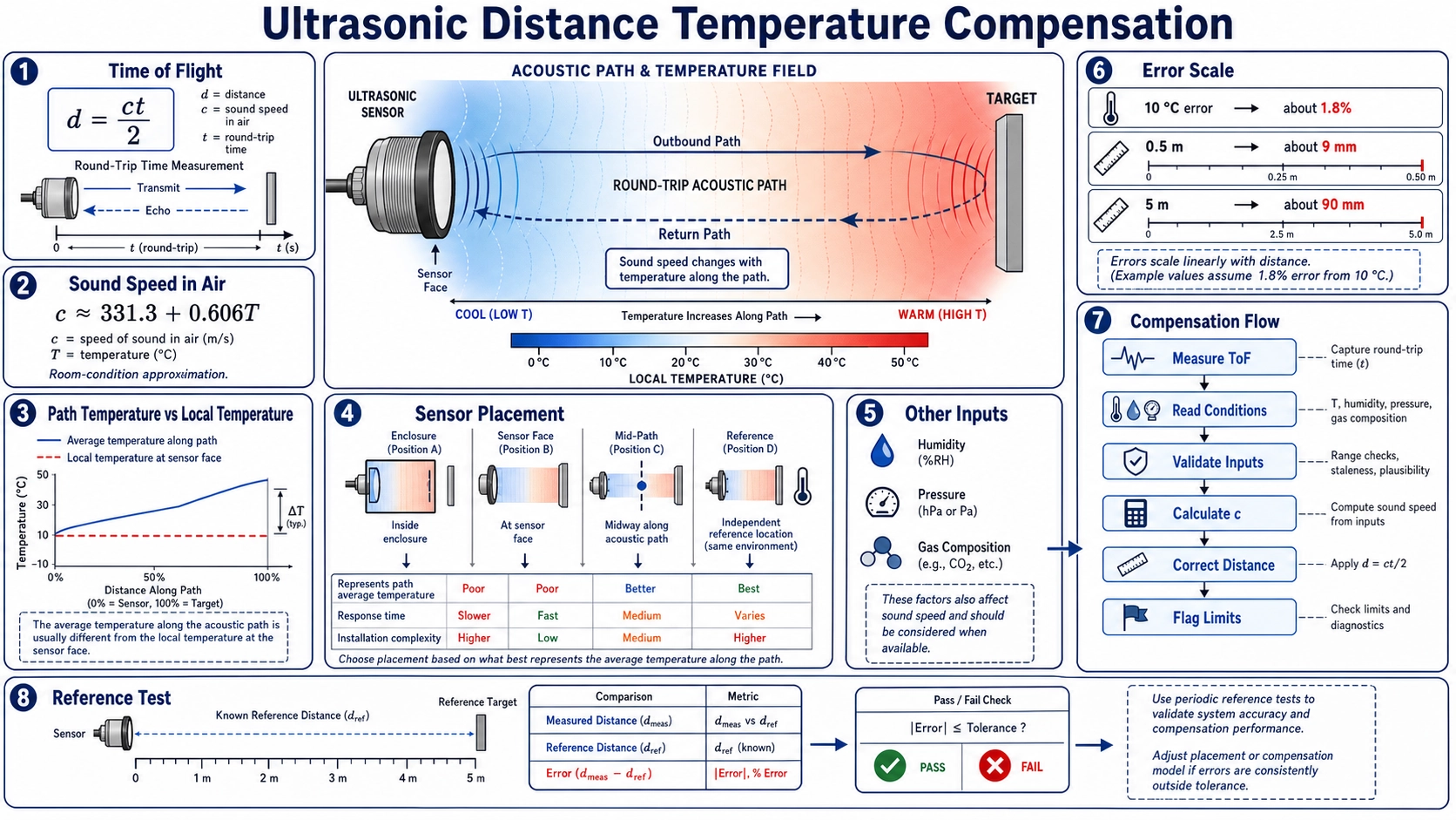
Temperature compensation corrects sound speed, not the echo timer
An ultrasonic distance sensor measures propagation time. It converts that time into distance using an assumed or calculated speed of sound. In air, sound speed changes strongly with temperature and also depends on humidity, pressure, carbon-dioxide concentration, and gas composition. A precise timer can therefore produce a biased distance when its sound-speed model does not represent the acoustic path.
Compensation is more than adding a temperature sensor beside the electronics. The temperature reading must represent the gas through which the pulse travels, respond at the required speed, and enter a valid sound-speed model with the correct units. The finished system then needs verification across distance and environment. This article focuses on pulse-echo distance measurement in air; formulas for air must not be reused for another gas or for water without an appropriate property model.
Start from the time-of-flight equation
For a simple pulse-echo path, the target distance is one-half of the propagation time multiplied by the path-effective sound speed:
distance = sound speed × round-trip time / 2
The factor of two accounts for travel to the target and back. System delays, ring-down, detection threshold, filtering, target response, and acoustic-center location may add offsets that must be characterized separately. Temperature compensation should not be used to conceal those delays.
If the actual path speed is cactual but the calculation uses cassumed, the indicated distance is approximately the true distance multiplied by cassumed/cactual. If air is warmer than assumed, its sound speed is normally higher and a calculation using the colder, lower speed will under-report distance. The sign reverses when the assumed speed is too high.
A useful air approximation and its boundary
Near ordinary room conditions, a common engineering approximation for dry air is:
c ≈ 331.3 + 0.606T metres per second, where T is air temperature in degrees Celsius.
This relation is useful for estimating the dominant temperature trend, not for claiming reference-level accuracy over arbitrary humidity, pressure, composition, or temperature. Around 20 °C, its slope corresponds to roughly 0.18% change in sound speed per degree Celsius. A 10 °C temperature error can therefore create a distance error on the order of 1.8%, or about 9 mm over a 0.5 m path and 90 mm over a 5 m path, before other error sources. These are approximate scale examples, not guaranteed sensor specifications.
For a higher-accuracy air model, use a validated formulation over its published range. Cramer’s 1993 work on the speed of sound in air includes temperature, humidity, pressure, and carbon-dioxide concentration. The model inputs and applicable range must be implemented correctly; adding a complex equation does not improve a system if the humidity sensor is absent or the temperature does not represent the path.
What temperature should the algorithm use?
Travel time accumulates along the entire acoustic path. In uniform air, one representative temperature can be adequate. In a gradient, the correct effective speed is related to propagation through all path segments, not simply the arithmetic average of two convenient sensors. Hot equipment, sunlight, a heated tank wall, refrigeration, ventilation jets, exhaust, and stratification can produce a path that differs from the temperature inside the sensor housing.
| Sensor location | Advantage | Failure mode | Mitigation |
|---|---|---|---|
| On the electronics PCB | Low cost and easy integration | Self-heating and enclosure temperature differ from the air path | Characterize offset and power dependence; avoid treating PCB temperature as ambient without evidence |
| Near the transducer face | Closer to the launch region | Face, housing, sunlight, or process wall conducts heat into the sensor | Provide airflow exposure and thermal isolation consistent with environmental protection |
| External ambient probe | Can sample free air away from electronics | May not represent a long or stratified path; cable and placement add risk | Define a repeatable location and compare against path gradients |
| Multiple path sensors | Provides information about gradients | More channels, calibration, wiring, and model complexity | Use when uncertainty analysis shows a single point is inadequate |
Thermal lag matters during change
A temperature sensor may be accurate at equilibrium yet wrong during a rapid transition. Its package, protective enclosure, potting, airflow, and contact with the housing determine response time. The acoustic air path may change in seconds while a protected sensor responds over a much longer period. This creates a temporary distance bias after a door opens, ventilation starts, a process heats, or the device moves between environments.
Measure step response in the final assembly, not only the bare sensor datasheet. Record the ultrasonic result, reference temperature at relevant path positions, and embedded temperature simultaneously. A software filter can reduce noise but adds more lag. Select filtering from the real environmental rate of change and the application’s response requirement.
Humidity, pressure, and gas composition
Water vapour changes the thermodynamic properties and molecular composition of air, so humidity affects sound speed. Atmospheric pressure also enters accurate real-gas formulations, even though the simplest ideal-gas expression suggests little direct pressure dependence at fixed composition and temperature. Carbon dioxide concentration matters in precision work. For ordinary industrial ranging, temperature may dominate, but the uncertainty budget should determine whether other inputs can be ignored.
Never apply an air model to nitrogen, carbon dioxide, natural gas, refrigerant vapour, or a changing process gas. Gas composition can change sound speed enough to dominate temperature compensation. Where composition varies, a separate composition measurement, a calibration for defined mixtures, a different measurement principle, or an algorithm that estimates sound speed from another path may be necessary.
Compensation cannot fix acoustic geometry
- Target angle and material: a weak or distorted echo changes the detected time.
- Beam and nearby structures: the strongest echo may switch between the intended target and an off-axis object. See the ultrasonic transducer beam-angle guide.
- Ring-down and receiver recovery: close targets may be masked regardless of sound-speed accuracy.
- Threshold walk: amplitude changes can move the detected crossing time.
- Air movement and turbulence: wind components and temperature fluctuations alter propagation and beam path.
- Condensation, frost, or contamination: the transducer response and matching layers can change.
- Mechanical reference: distance may be required from a housing face while the acoustic centre lies elsewhere.
These effects need optical/mechanical reference tests, waveform inspection, target control, and installation design. A temperature coefficient applied to a false echo only makes the wrong target distance more systematically wrong.
Design the compensation chain
- Define the medium and composition range. Select a sound-speed model valid over temperature, humidity, pressure, and composition requirements.
- Choose temperature and any additional sensors from the uncertainty budget, not from convenience alone.
- Place sensors so their reading represents the acoustic path and characterize self-heating, radiation, conduction, and airflow effects.
- Calibrate or verify each environmental channel with traceable references over the required range.
- Implement units, range checks, invalid-sensor handling, startup behavior, filtering, and timestamps explicitly.
- Keep raw time of flight and raw environmental values available for diagnosis; do not store only compensated distance.
- Separate fixed delay/offset calibration from sound-speed compensation and preserve both coefficients with version control.
Verification matrix
Use mechanically stable reference distances traceable to an appropriate standard. Test more than one distance because a sound-speed error is mainly proportional to distance while a fixed electronic or acoustic delay appears mainly as an offset. Include temperatures spanning the operating range, both rising and falling transitions, and the expected humidity or gas conditions. Allow equilibrium tests and dynamic step tests.
| Variation | What it separates | Evidence to save |
|---|---|---|
| Multiple distances at one stable environment | Scale error versus fixed offset and target effects | Raw time, waveform, temperature, reference distance, residual plot |
| Multiple stable temperatures | Sound-speed model and sensor offset | Path reference temperatures, embedded reading, humidity/pressure if used |
| Heating and cooling ramps | Thermal lag and hysteresis | Synchronized time series and assembly state |
| Target and angle changes | Threshold walk and false echoes versus compensation | Waveforms, echo selection, amplitude and geometry |
| Power and duty-cycle changes | Self-heating and timing interaction | Supply, duty cycle, internal temperature and distance |
Fit and evaluate the model using separate data sets where possible. Report maximum residuals and uncertainty over the stated range, not only average error at one laboratory condition. The ultrasonic distance sensor selection guide covers the other range, frequency, beam, blind-zone, and output decisions that must accompany compensation.
Common implementation mistakes
- Using PCB temperature without measuring self-heating.
- Applying a Celsius formula to a Kelvin value or mixing metres, millimetres, seconds, and microseconds.
- Using one-way time with a pulse-echo factor of two, or dividing a through-beam path by two.
- Clamping out-of-range temperature to the model limit without raising a diagnostic.
- Filtering temperature much more slowly than the environment while leaving distance unfiltered.
- Calibrating an offset at one distance, then calling the result temperature compensation.
- Testing only after thermal equilibrium and missing transient error.
FAQ
How much does one degree Celsius change an ultrasonic distance?
Near room temperature in ordinary air, the simplified slope corresponds to about 0.18% per degree Celsius in sound speed. The exact distance error depends on the assumed and actual path conditions and the sound-speed model.
Can the temperature sensor be placed inside the enclosure?
Only if testing shows that it represents path air over power, sunlight, airflow, and transient conditions. PCB and enclosure temperature often include self-heating and thermal lag.
Does humidity compensation always need a humidity sensor?
If the required uncertainty makes humidity significant, the algorithm needs a valid humidity input or a justified bounded assumption. Adding humidity to the equation without measuring or constraining it does not reduce uncertainty.
Can calibration at one temperature replace compensation?
No. One-point calibration can correct a fixed offset at that condition. It does not model the change in propagation speed or thermal lag across the operating range.
Reference model and engineering inputs
For a higher-accuracy treatment of air, see Owen Cramer’s 1993 paper on the speed of sound in air. Verify the model’s range, variables, units, and implementation against the original publication before using it as a metrological claim.
For a compensation design review, send Deep Minds Ultrasonic the gas composition, distance range, temperature and humidity range, gradient sources, target, enclosure, duty cycle, sensor positions and response times, raw time-of-flight format, required error, reference method, and production quantity. These inputs determine whether a simple local sensor is adequate or path characterization is required.