Start with the measurement volume, not just the nominal frequency
An ADCP transducer has to do more than produce a strong echo in a tank. In an acoustic Doppler current profiler, several acoustic channels must provide usable observations of water motion within a defined measurement geometry. Frequency, beam shape, transmit and receive behavior, and channel-to-channel variation therefore belong in the same selection discussion. Choosing each one separately can leave a development team with individually acceptable components that do not work well together.
This guide focuses on transducers for ADCP development, rather than the selection of a finished current profiler. The useful starting point is a measurement brief: the intended water environment, first and last useful cells, required spatial detail, expected current conditions, mounting arrangement, and available electronics. A component frequency does not, by itself, establish profiling range or water-velocity accuracy.
Turn the application brief into acoustic requirements
| Development question | Selection consequence | Evidence to compare |
|---|---|---|
| Where must valid measurements begin and end? | Balance attenuation and return strength against the required sampling window. | Received waveforms, noise and recovery under representative water conditions. |
| How small is the feature or measurement cell? | Consider pulse timing and bandwidth as well as beam footprint. | Actual transmitted burst and processed range-cell response. |
| How will the beams cross the flow? | Separate beam width from axis inclination and mechanical alignment. | Directional response and the assembled head’s geometry. |
| How many channels must behave alike? | Specify a matched set, not only individual nominal limits. | Comparable acoustic and electrical records for every channel. |
Describe the environment beyond a label such as “river” or “ocean.” Temperature, suspended material, bubbles, nearby boundaries and the installation’s own wake can change the usable signal. The acoustic return normally depends on scatterers moving with the water; scattering conditions cannot be replaced by a promise based on frequency alone. Representative test conditions should consequently be part of the brief, not an activity deferred until the end.
Frequency is a trade-off, not a ranking
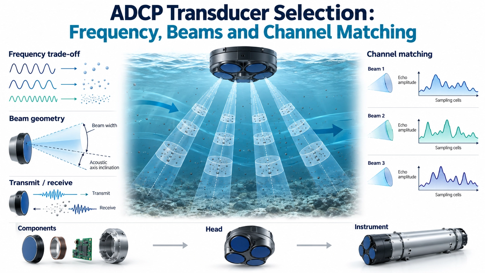
Higher frequency generally increases acoustic absorption in water, while also changing wavelength and the interaction with scatterers. Lower frequency may be attractive when propagation loss is important, but it does not automatically provide sufficient return, suitable beam control or the desired spatial detail. Aperture, packaging and the transmitted signal still matter. Two designs at the same frequency can have very different directional and transient behavior.
The BBUA-ADCP Doppler current measurement transducer series provides a concrete starting point with nominal configurations at 500 kHz, 1 MHz, 2 MHz and 3 MHz. Treat each as a complete configuration to evaluate, rather than combining the frequency from one version with the beam or electrical characteristics of another. These are transducer options, not a guarantee that a finished instrument will achieve a particular profiling depth or current accuracy.
For an initial comparison, hold the candidate mounting geometry and measurement objective constant. Then examine the return over the intended observation window using an appropriate burst and receiver setting for each candidate. Document any changes in excitation or gain: a stronger recorded trace obtained with more drive or more gain is not, on its own, evidence of a better transducer. Do not use an electrical maximum as a default operating setting.
Keep beam width, beam inclination and head attitude separate
Beam width describes the angular extent of the acoustic response under a stated measurement convention. Beam inclination describes where the acoustic axis points relative to the instrument. Head attitude describes the orientation of the assembled instrument in the water. Confusing these three quantities can turn an apparently narrow beam into a poorly defined sampling geometry.
Before using a catalogue angle in a footprint calculation, establish whether it is a full angle or half angle, which response level defines it, and how it was measured. The guide to ultrasonic transducer beam angle explains those definitions. For an ADCP project, extend that information to the actual head: acoustic-axis orientation, mounting references, nearby housing surfaces and boundary echoes should be assessed together. A narrow main lobe does not eliminate side-lobe or boundary interference.
A Doppler channel measures motion projected along its beam. Reconstructing velocity components from several beams also depends on their geometry and on the flow assumptions used by the processor. Spatially separated beams can encounter different flow near a wall, obstruction or strong shear. Better electrical matching cannot correct that physical difference. The USGS report Measuring Discharge with Acoustic Doppler Current Profilers from a Moving Boat, particularly appendices A and D, provides useful background on beam-coordinate transformations and alignment checks. Its instrument-specific acceptance values should not be transferred to a new transducer design.
Define what a matched channel set must demonstrate
Matching resonant frequency alone is insufficient. Channels with similar impedance minima can still differ in transmitted output, receiving response, ringing or acoustic-axis direction. Conversely, a modest electrical difference does not automatically create an unacceptable velocity error. What matters is its effect on the selected signal-processing method and operating window.
- Electrical behavior: compare water-loaded impedance over the intended operating band, with the specified cable and termination.
- Transmit response: compare burst shape, relative output and decay using controlled excitation and a repeatable acoustic arrangement.
- Receive response: compare relative sensitivity, usable bandwidth and waveform shape with the same incident signal and receiver conditions.
- Timing and recovery: examine relative delay, phase behavior where relevant, and the time until useful reception resumes after transmission.
- Geometry: check acoustic-axis direction and directional response against the mechanical datums used to assemble the head.
Use the actual cable lengths, transmit/receive switching, protection and front end when confirming the final set. They can change loading, saturation and recovery. General circuit considerations are covered in the transducer circuit-matching guide; the additional ADCP requirement is that the channels remain comparable under the same acquisition strategy. Record individual traces, not only an averaged pass result that could conceal an outlier.
Set channel limits from the instrument’s error budget and processing needs. There is no universal phase, sensitivity or delay tolerance that can be assigned solely from a nominal frequency. In particular, do not assume every fixed delay translates directly into a Doppler velocity bias: its significance depends on the waveform, sampling and estimator. Relative changes across temperature and after assembly can be just as important as room-temperature agreement.
Validate the set in stages, then validate the instrument
- Establish a repeatable comparison. Fix water temperature, immersion, alignment, target or reference receiver, cables, burst settings and acquisition settings. Identify each transducer and channel.
- Separate component and electronics effects. Exchange channels or components where practical. A difference that follows the electronics requires a different investigation from one that follows a transducer.
- Repeat in the assembled head. Check geometry, coupling through the structure, channel interference, recovery and the usable observation window. A successful isolated-element test is not an assembled-head result.
- Check temperature and representative operation. Repeat the relevant comparisons across the intended conditions, then compare complete velocity results with an appropriate independent reference. Still water alone cannot establish accuracy in moving water.
Close the selection review with a defined configuration: chosen frequency, beam convention and axis geometry, cable and electronics conditions, channel-matching measurements, environmental envelope, and the agreed verification method. Include how replacement units will be compared with an existing set. That gives Deep Minds Ultrasonic and the development team a meaningful basis for discussing BBUA-ADCP candidates without confusing component acceptance, multichannel matching and finished-instrument calibration.