Installation affects metering performance
An ultrasonic water meter measures the transit-time difference between signals travelling with and against the water flow. The electronic calculation may be accurate, but the measurement still depends on the hydraulic condition inside the meter body. Air, an incompletely filled pipe, severe flow disturbance, a misaligned gasket, reverse installation, or incorrect scaling can create a poor result even when the meter itself is functional.
This article focuses on field installation and commissioning. For model, diameter, communication, valve, and application selection, see our DN15 to DN500 ultrasonic water meter selection guide.
Confirm the meter and project data before installation
- Nominal diameter and connection type
- Required flow range and range ratio
- Temperature and pressure class
- Permitted installation orientation
- Upstream and downstream flow-profile sensitivity class
- Communication interface, power supply, and cable length
- Direction of normal and possible reverse flow
- Accessibility for reading, service, valve operation, or battery replacement
Do not choose the installation point only because it is physically convenient. The pipe should remain full, the electronics should be accessible, and the meter should not be exposed to conditions outside its environmental rating.
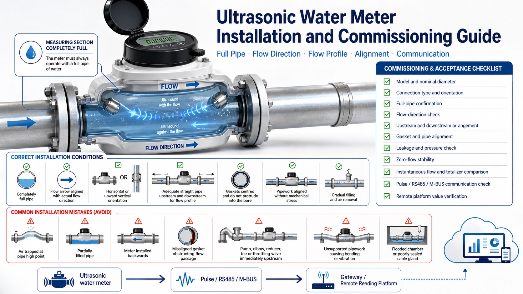
Keep the measuring section completely full
Transit-time water measurement requires a continuous liquid path between the transducers. Large air pockets, partial filling, or repeated entrained air can interrupt or distort the acoustic signal. Avoid the highest point of a pipeline where air naturally collects. A rising pipe section or a vertical section with upward flow is often preferable to a location where water can drain away.
| Location | Assessment | Reason |
|---|---|---|
| Pipe high point | Usually avoid | Air can accumulate in the meter |
| Downward vertical flow | Evaluate carefully | The pipe may not remain full at low demand |
| Upward vertical flow | Often suitable if approved | Helps maintain a full measuring section |
| Immediately after an open discharge | Avoid | Pipe may be partially filled |
| Flood-prone chamber | Use only with suitable IP protection | Connector, cable, and enclosure must tolerate immersion conditions |
Follow the flow arrow and approved orientation
Install the meter so the body arrow matches normal flow. Some meters can measure reverse flow, but this does not mean the body may be installed backwards without affecting display conventions, valve logic, or project acceptance. Confirm whether the register stores forward and reverse volume separately.
Horizontal and vertical installation may both be allowed, but the metrological performance or range ratio may differ by orientation for a specific model. Use the orientation shown in the product documentation and do not infer permission from another meter with a similar body.
Manage upstream disturbances according to the meter specification
Elbows, pumps, control valves, partially open valves, reducers, and tees can create swirl or asymmetric velocity profiles. The required upstream and downstream conditions are model-specific. Some approved meter designs carry flow-profile sensitivity classes such as U0/D0 or U5/D3; other products require defined straight lengths.
Use the actual meter documentation as the governing requirement. Where possible, place throttling or control valves downstream rather than directly upstream, and avoid a pump discharge immediately before the meter. If the site cannot meet the stated installation condition, discuss the arrangement before commissioning instead of assuming software can correct it.
Prepare the pipe and align the gaskets
Flush welding slag, sand, sealant, scale fragments, and other debris before fitting the meter. Debris can damage the measuring channel, block a valve, contaminate the transducer windows, or create abnormal flow.
For threaded meters, support the pipe so tightening torque is not transferred through the body. Use the specified unions and seals. For flanged meters, align the flanges without forcing the meter into position. Gaskets must be centred and must not protrude into the bore. A gasket intruding into the flow passage can create disturbance and reduce the effective diameter.
Protect the meter from mechanical and environmental stress
- Do not use the meter as a pipe support or step.
- Avoid excessive bending, torsion, and vibration from unsupported pipework.
- Provide drainage or suitable enclosure protection in chambers where flooding is possible.
- Keep communication and pulse cables separated from high-power cables where practical.
- Maintain cable gland sealing and do not leave unused entries open.
- Protect displays and plastics from conditions beyond the rated sunlight and temperature limits.
Electrical and communication checks
Before applying power or connecting a network, verify supply voltage, polarity, pulse output type, RS485 A/B designation, M-BUS wiring, shield connection, and any external antenna or gateway requirement. Network commissioning should record the meter address, baud rate, protocol, register map, communication identifier, SIM or wireless profile where applicable, and the unit used by the platform.
A communication link can be active while values remain wrong because the wrong register, decimal factor, signed format, or unit has been selected. Compare instantaneous flow and total volume at the meter and at the remote platform.
Fill and pressurize the line gradually
- Confirm that the meter and joints are mechanically secure.
- Open valves slowly to fill the line and displace air.
- Check for leakage before full pressure is applied.
- Allow the pipe to become completely full.
- Check that the meter reports a stable zero when flow is stopped.
- Create a known flow and confirm the indicated direction.
- Compare totalized volume with a suitable reference where project acceptance requires it.
Do not use an unstable, air-filled startup period as the acceptance result. If the meter has empty-pipe or acoustic-signal diagnostics, record their status after the line is fully filled.
Commissioning and acceptance record
Record the model, serial number, diameter, orientation, flow arrow, pipe location, upstream and downstream arrangement, installation photos, pressure test, leakage result, zero-flow reading, instantaneous-flow comparison, totalizer comparison, communication settings, platform value, and final acceptance status. For projects comparing metrological specifications, our guide to Q1, Q2, Q3, Q4, and R ratio explains how the declared flow ranges should be interpreted.
Deep-Minds supplies ultrasonic smart water meters for remote reading and other small- and large-diameter metering configurations. Final installation rules must follow the selected model and applicable project standard.
FAQ
Can an ultrasonic water meter be installed vertically?
Many models allow vertical installation, often with upward flow, but the approved orientation and declared performance must be checked for the exact model.
Is a straight pipe always required?
The requirement depends on the meter’s flow-profile sensitivity class and product instructions. Do not apply one generic straight-length rule to every ultrasonic water meter.
Why does the meter show no flow after installation?
Check that the pipe is full, the flow direction is correct, isolation valves are open, air has been removed, the meter is powered, and the display or platform is using the correct units and register.