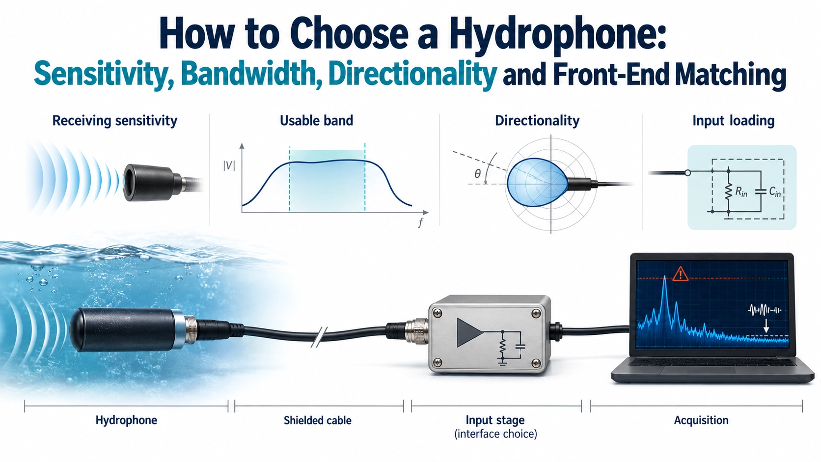
A sensitivity number is not a complete listening specification
A hydrophone converts underwater sound pressure into an electrical signal. For sound recording, machinery-noise studies or environmental monitoring, choosing the receiving element is only one part of designing the measurement chain. A sensitive element connected to an unsuitable input can lose low-frequency response, pick up interference or overload the recorder. A clean-looking waveform can still have the wrong pressure scale.
Before comparing models, decide whether the task is event detection, relative spectral comparison or measurement of absolute sound-pressure levels. These tasks require different evidence. State the frequency band, weakest useful signal, largest expected event, deployment arrangement and recording duration. Do not treat a catalogue listening distance as a universal detection range: source strength, propagation, background noise, bandwidth and the detection criterion all affect the result.
Read receiving sensitivity with its reference conditions
Voltage receiving sensitivity is the ratio of output voltage to incident sound pressure. It can be expressed in V/Pa or as a logarithmic level, commonly dB re 1 V/µPa. A negative value in that convention is normal; it does not mean negative pressure or poor performance. With the same reference and conditions, a less negative value represents more output voltage per unit pressure, but not necessarily lower system noise or a better recording.
A meaningful comparison also identifies frequency, direction of incidence, acoustic-field convention, electrical load, cable and whether a preamplifier is included. Open-circuit element sensitivity and the sensitivity of a loaded, amplified assembly are not interchangeable. Pressure calibration and free-field calibration describe different conditions. The National Physical Laboratory’s hydrophone calibration services distinguish receiving sensitivity, directional response and electrical impedance measurements; one measurement does not establish all three.
A worked example, not a product specification
Suppose a hypothetical hydrophone has a voltage sensitivity of -180 dB re 1 V/µPa at the frequency being evaluated. This equals 10-9 V/µPa, or 1 mV/Pa. A sinusoidal pressure of 1 Pa RMS would therefore produce 1 mV RMS under those stated conditions. A subsequent voltage gain of 10 would produce 10 mV RMS at the acquisition input, assuming a linear chain without additional loading loss.
The same 1 Pa RMS pressure corresponds to 120 dB re 1 µPa. That pressure level and the negative sensitivity level use different references and describe different quantities. These illustrative numbers are not BBUA-H7K specifications. For real measurements, use the relevant frequency-dependent calibration and the complete chain gain before converting recorded voltage to pressure.
Choose a usable band and a known receiving direction
A centre frequency, a resonance and a useful receiving band answer different questions. For noise analysis, define the band over which response variation is acceptable for the intended analysis. A narrow response peak may help detect a particular tone while distorting a broader spectrum if treated as flat. Filters, cable loading, housing and the front end can further change the effective response.
The BBUA-H7K hydrophone and underwater noise receiver provides a product example with a standard centre-frequency specification of 7 kHz ±1 kHz and capacitance of 8,000 pF ±20% measured at 1 kHz. The centre-frequency tolerance is not a statement of receiving bandwidth or flatness. The capacitance is a useful electrical input, not a substitute for a sensitivity curve or complete source-impedance data.
Directionality also needs a frequency and a reference orientation. Do not assume that a compact hydrophone receives equally from every direction, particularly after installation beside a frame, wall or vessel structure. For a fixed sound source, document orientation and evaluate the relevant angular response. For changing sound fields, assess how mounting and direction-dependent response affect comparisons between deployments.
Match the front end to the actual output architecture
First establish whether the device presents a passive high-impedance output or an already buffered output. A passive capacitive source, a powered voltage-output assembly and a charge-amplifier arrangement require different interfaces. Do not infer a power supply, connector function or amplifier topology from a model name. The transducer circuit-matching guide covers general loading principles; for hydrophones, the priority is preserving the receiving transfer function rather than matching a transmit driver.
| Part of the receiving chain | What to establish | Consequence if overlooked |
|---|---|---|
| Hydrophone, cable and input | Output type, impedance versus frequency, cable capacitance and intended load. | Changed sensitivity or loss of low-frequency response. |
| Preamplifier | Input voltage/current noise, gain, bandwidth and overload limit. | Weak signals obscured or strong events clipped. |
| Shielding and installation | Ground arrangement, cable motion, strain relief and distance from power equipment. | Electrical pickup or mechanically induced artefacts mistaken for sound. |
| Acquisition and filtering | Input range, analogue anti-alias filtering and sample rate. | Clipping, lost resolution or out-of-band energy folded into the recording. |
| Conversion to pressure | Frequency response, gain settings, calibration reference and processing units. | Incorrect sound-pressure levels despite plausible waveforms. |
For a passive capacitive source read by a voltage input, added cable and input capacitance can change effective voltage sensitivity. Input resistance and the source’s effective capacitance also influence the low-frequency corner. A longer cable is therefore not automatically an electrically neutral extension. A charge amplifier is another possible approach, but its suitability depends on the device and application; voltage sensitivity and charge sensitivity must not be substituted for each other.
Evaluate noise over the required band, not by comparing isolated noise numbers with different units or bandwidths. Amplifier voltage noise, current noise interacting with source impedance and the recorder all contribute. A quiet-water recording also includes ambient sound, flow, mounting effects and interference, so it is not automatically a measurement of hydrophone self-noise. More gain does not improve the signal-to-noise ratio already present at the amplifier input, although suitable gain can reduce the recorder’s relative contribution.
Reserve headroom for loud events as well as sensitivity for weak ones. Check both the preamplifier and converter for overload. Sampling above twice the highest retained frequency is a theoretical minimum, not a complete acquisition design: analogue anti-alias filtering and its transition band still need to be considered. Keep acquisition gain and filter settings with every recording.
Use symptoms to separate acoustic and electrical problems
Low frequencies disappear after a cable or input change.Compare the loading and coupling/filter response before concluding that the source became quieter. Repeat the comparison with the original configuration.A narrow line follows nearby electrical equipment.Investigate grounding, shielding and pickup, while also checking whether the equipment genuinely produces underwater sound. Frequency coincidence alone does not distinguish the two.Strong events look flattened while quiet periods look normal.Inspect overload through the whole chain. Reducing digital playback level cannot recover a waveform clipped before or during conversion.
Ask for evidence that follows the complete recording chain
Use the general transducer testing guide for controlled electrical and acoustic checks, then add hydrophone-specific evidence: a sensitivity response with stated load and cable, directional conditions, a defined noise-assessment method, and documented gain and filtering. Acoustic comparison needs controlled geometry, reflections and water conditions, with an appropriate reference and uncertainty statement when absolute levels matter. Electrical signal injection can verify downstream electronics but cannot replace acoustic calibration of the hydrophone.
For a discussion with Deep Minds Ultrasonic, bring the target sound band, relative or absolute measurement objective, expected level range, mounting direction, environment, cable arrangement and acquisition-input details. Treat the BBUA-H7K as a receiving component to evaluate within that chain. A defensible selection ends with a known transfer function and validation method, not merely a centre frequency or a visually attractive recording.