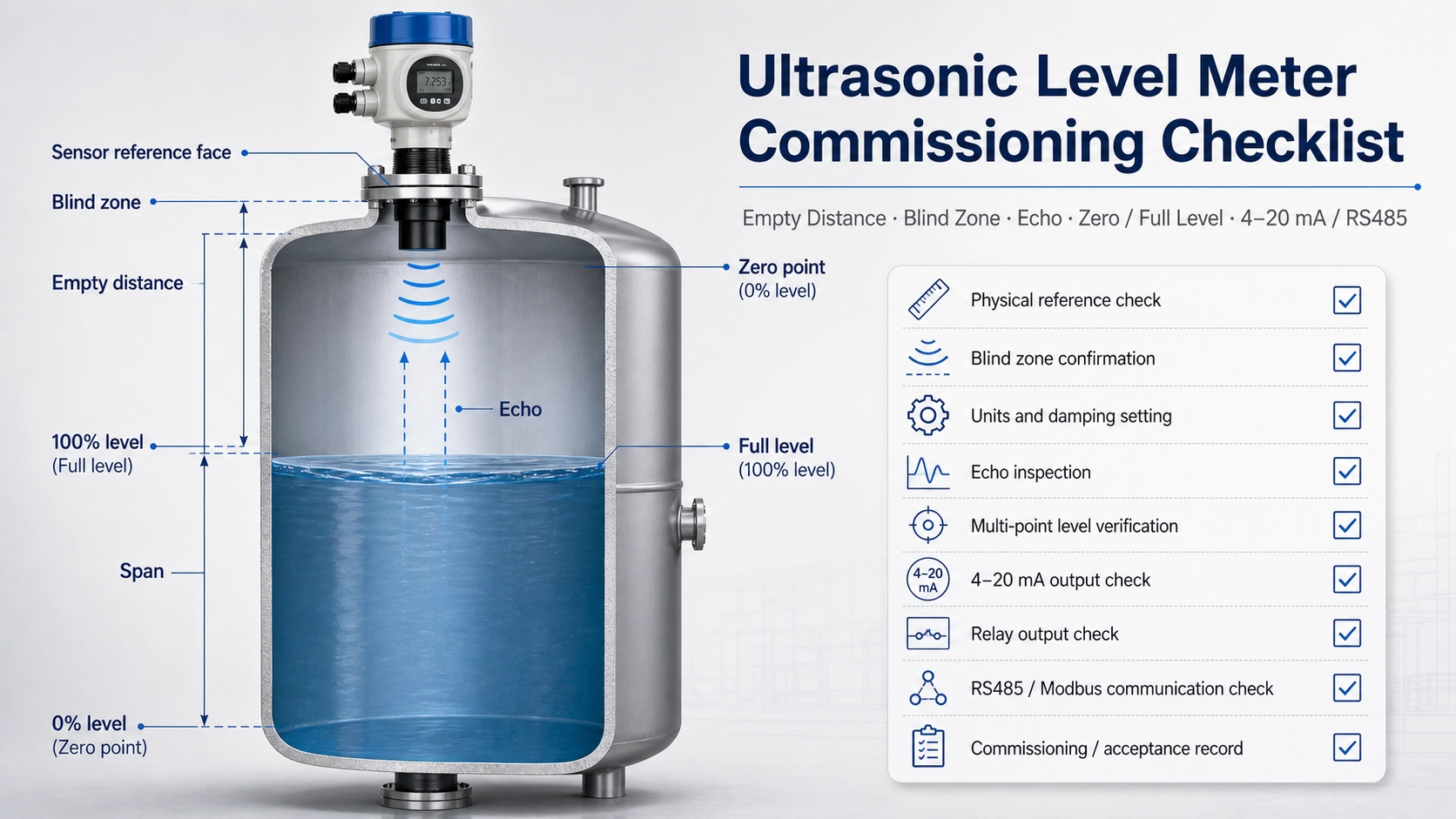
Commissioning is not the same as installation
Correct mounting gives an ultrasonic level meter a usable acoustic path. Commissioning confirms that the instrument converts that path into the correct level value and sends the correct signal to the PLC, telemetry unit, display, or alarm system. A meter can be mounted neatly and still report the wrong level if the empty distance, tank height, output range, or reference point has been entered incorrectly.
This checklist is intended for top-mounted non-contact ultrasonic level meters. Bottom-mounted external systems use a different acoustic arrangement and should be commissioned according to their own coupling and vessel requirements. For a comparison of instrument architectures, see our ultrasonic level meter types guide.
Record the physical reference before entering parameters
Do not begin with the menu. First establish the physical dimensions that the configuration will represent. Measure from the sensor reference face, not from the enclosure lid, mounting thread, or tank roof unless the manual explicitly defines that point.
| Parameter | What it represents | Common mistake |
|---|---|---|
| Empty distance | Distance from the sensor reference face to the 0% level or tank bottom reference | Using the external tank height instead of the acoustic distance |
| Full level | Highest valid process level | Setting 100% inside the blind zone |
| Span | Difference between the configured 0% and 100% points | Mapping the output to a different span than the display |
| Offset | Correction between the physical reference and the required process datum | Using offset to hide an installation error |
Record the nozzle height, sensor projection, tank bottom geometry, highest safe level, lowest operating level, and any inaccessible zone. These values should remain in the commissioning record so that future technicians can understand why the settings were chosen.
Confirm the blind zone and highest measurable level
After transmitting a pulse, the transducer and receiver require a short recovery period. Echoes arriving during this interval may not be measured reliably. This creates the near-field blind zone. The configured full level must leave sufficient clearance below the sensor face under all expected conditions, including overfill margin, foam, waves, and process surges.
- Check the blind-zone value for the actual model and range.
- Measure the distance from the sensor face to the highest expected surface.
- Include nozzle depth and any sensor recess in the calculation.
- Do not reduce the blanking distance merely to force a reading at an unsuitable mounting height.
Set zero, full level, units, and damping
Enter the empty distance or tank height according to the instrument’s configuration logic. Some meters ask for distance; others ask for level. Confirm the display units before entering values, especially where millimetres and metres or inches and feet may be mixed.
Set the 0% and 100% points, then configure damping or response time. Fast response is useful when the process changes quickly, but excessive responsiveness can make agitation appear as unstable level. Heavy damping produces a smoother trend but can delay alarms. Choose a value that reflects the real process dynamics rather than using the maximum smoothing setting by default.
Check the echo before changing calibration
Use the echo curve, signal-strength display, diagnostic value, or raw distance screen if the instrument provides one. The primary echo should correspond to the manually measured surface distance. Fixed reflections from a nozzle lip, ladder, brace, pipe, agitator, or tank wall may appear at repeatable distances.
If a false echo is stronger than the process echo, correct the mounting position or acoustic path first. False-echo suppression or mapping can be useful for permanent structures, but it should not be used to mask a moving obstruction or a poorly positioned sensor. Perform any false-echo learning with the tank at the condition required by the instrument, usually when the relevant obstacles are exposed.
Verify the reading at more than one level
A single-point comparison can confirm an offset, but it cannot confirm the entire span. Compare the displayed level or distance against an independent reference at several points during filling or emptying. Suitable references may include a sight glass, dip measurement, calibrated scale, known transfer volume, or another verified instrument.
- Check the low-level region without entering the minimum reliable echo condition.
- Check one or more intermediate levels.
- Check the high-level region while maintaining blind-zone clearance.
- Observe the reading during process movement, not only after the surface becomes still.
- Record the surface condition, temperature, agitation, foam, and signal status for each comparison.
Verify 4–20 mA, relay, and RS485 outputs separately
The local display may be correct while the control system value is wrong. Treat each output path as a separate test.
| Output | Commissioning check | Typical source of mismatch |
|---|---|---|
| 4–20 mA | Measure loop current at defined level points and confirm the PLC scaling | Reversed 0% and 100%, wrong engineering range, loop power or wiring issue |
| Relay | Test setpoint, hysteresis, delay, and fail-safe state | Alarm configured from distance while the operator expects level |
| RS485/Modbus | Confirm address, baud rate, parity, register, data type, and byte order | Correct communication but wrong register interpretation or scaling |
| Remote platform | Compare the transmitted value and timestamp with the local instrument | Gateway conversion, stale data, unit conversion, or polling interval |
Create a commissioning and acceptance record
The final record should identify the instrument model and serial number, installation position, sensor reference point, tank dimensions, configured range, blind zone, damping, false-echo settings, output scaling, communication parameters, comparison readings, and acceptance result. Photos of the mounting position and the internal beam path are often more useful than a brief note written months later.
For recurring faults after commissioning, use our ultrasonic level meter troubleshooting guide. Deep-Minds can also review tank geometry, output requirements, and application conditions when selecting an integrated ultrasonic level meter or a split design.
FAQ
Should 4 mA represent an empty or full tank?
Either mapping is technically possible, but the convention must be defined consistently in the instrument, PLC, drawings, and operating documentation. Many level applications use 4 mA for 0% and 20 mA for 100%.
Can commissioning remove errors caused by a bad mounting position?
Configuration can compensate for a documented reference offset, but it cannot reliably correct an obstructed beam, severe false echoes, an inadequate blind-zone clearance, or a surface that does not return a usable echo.
Why should the meter be checked at several levels?
Multiple points reveal span, linearity, mapping, and process-dependent echo problems that a single comparison cannot show.