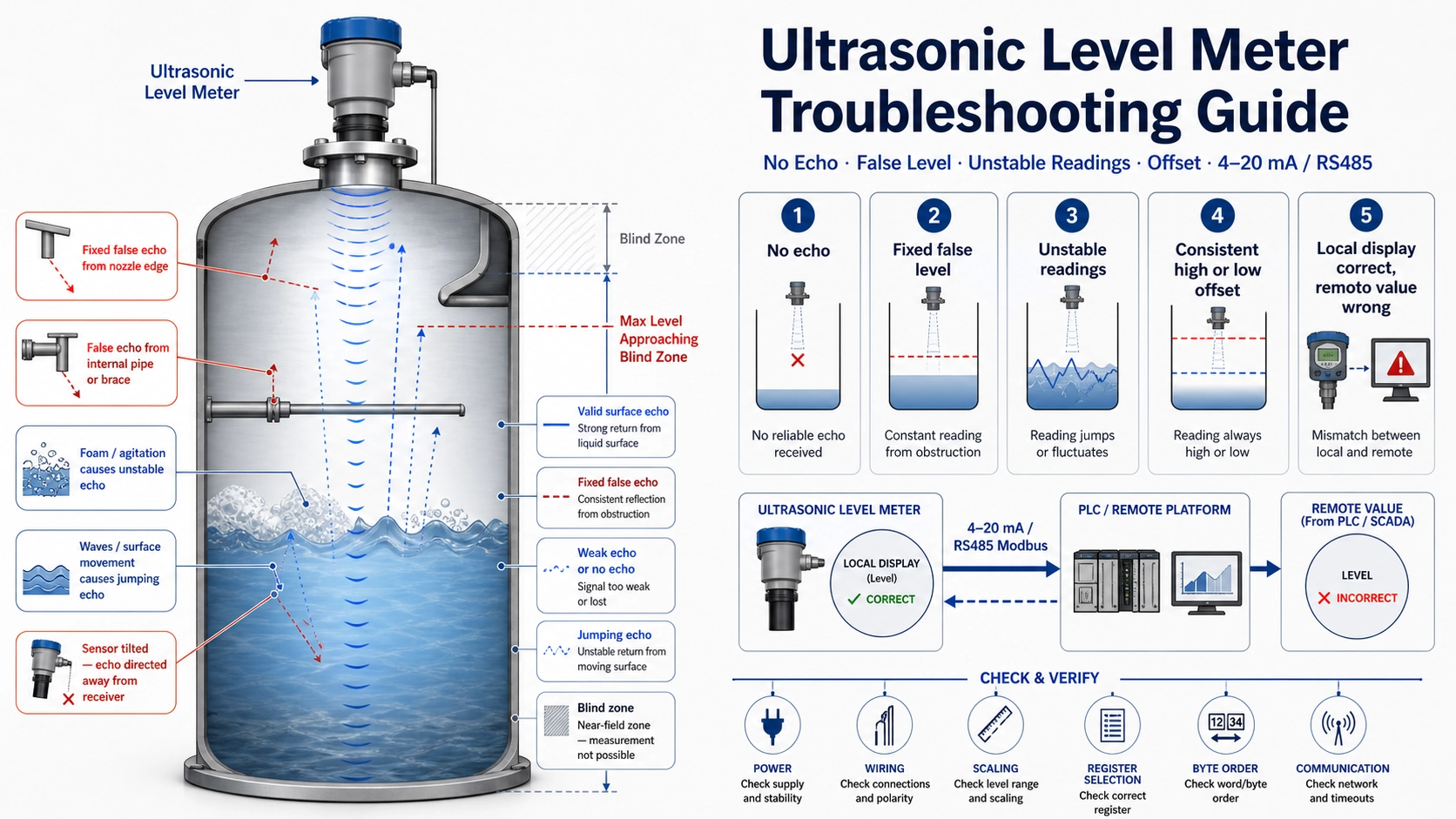
Troubleshoot from the symptom, not from an assumption
An ultrasonic level fault may come from the sensor, the installation, the process surface, the configuration, the power supply, or the control-system mapping. Replacing the instrument before separating these possibilities often reproduces the same fault with a new unit. Begin by recording the displayed level, raw distance, echo status, output value, process condition, and the time at which the problem occurs.
| Symptom | First checks | Useful clue |
|---|---|---|
| No echo or maximum distance | Range, blind zone, sensor face, mounting angle, surface condition | Does the fault follow level or process conditions? |
| Fixed false level | Nozzle, ladder, pipe, brace, wall reflection | Does the reported distance match a physical obstruction? |
| Unstable or jumping level | Agitation, inlet flow, foam, condensation, loose mounting | Is the raw distance unstable or only the output? |
| Consistent offset | Reference point, tank height, offset, units | Is the error nearly constant across the range? |
| PLC value differs from display | 4–20mA scaling, Modbus register, byte order, units | Is the local distance correct? |
No echo or loss of echo
First confirm that the surface is within the configured measuring range and outside the blind zone. A tank may physically contain liquid while the actual distance lies beyond the selected model’s usable range. Check that the sensor face is clean and not covered by condensation, deposits, paint, a protective film, or mechanical damage.
Then inspect the acoustic path. A tilted sensor may direct the echo away from the receiver. A sloping solid surface, thick foam, dense vapor, heavy dust, or severe turbulence may return too little energy. Compare the fault with process events such as heating, filling, aeration, mixing, or pressure release. If the echo disappears only under one condition, the process is a stronger suspect than the electronics.
A fixed false level
A fixed reading is often a real echo from the wrong target. Read the raw distance and compare it with the positions of the nozzle lip, internal pipe, ladder, agitator shaft, brace, weld, or tank wall. If the indicated distance remains constant while the true level changes, a permanent structure is likely dominating the echo.
Corrective actions include moving the sensor, extending it beyond a nozzle, changing the mounting orientation, or using the instrument’s false-echo mapping function. Do not simply adjust the level offset: an offset moves the displayed value but does not stop the instrument from tracking the wrong reflector.
Unstable or jumping readings
Determine whether the instability exists in the raw acoustic distance or only in the processed output. If the raw distance jumps, inspect the surface and mounting. Common causes include inlet streams, mixers, waves, foam patches, condensation droplets, vibration, and a sensor that is not firmly mounted. Moving the sensor away from the inlet or using a suitable stilling arrangement may help, but the stilling structure must remain clean and acoustically suitable.
If the raw distance is stable but the output jumps, check damping, output scaling, communication polling, data conversion, and control-system filtering. Excessive gain or an aggressive echo-tracking setting can also make the instrument alternate between two reflectors.
A reading that is consistently too high or too low
A nearly constant error usually points to the reference geometry or an intentional offset. Recheck the sensor reference face, empty distance, tank height, nozzle height, units, and whether the instrument is displaying distance or level. A proportional error that grows across the range is more likely to involve span, output mapping, or an incorrect tank conversion.
Temperature affects the speed of sound in the gas space. Many instruments compensate using an internal or external temperature measurement, but rapid gradients, hot vapor layers, or a sensor temperature that does not represent the full acoustic path can still create process-dependent error. Do not treat every temperature-related deviation as a simple fixed offset.
Local display correct, remote value wrong
When the local distance and level are correct, stop changing the acoustic settings. Test the signal chain.
- For 4–20mA, measure the loop current and confirm whether the instrument maps level or distance.
- Check the PLC engineering range, input type, loop supply, common reference, and cable polarity.
- For RS485/Modbus, verify address, baud rate, parity, register number, signed or unsigned data, decimal scaling, and byte order.
- For a gateway or cloud platform, compare timestamps to rule out cached or delayed data.
Intermittent faults
Intermittent faults require a timeline. Record whether the problem appears after rain, at a certain tank temperature, during pump operation, when a variable-frequency drive starts, or only at one level. Inspect cable glands, shielding, grounding, connector moisture, supply dips, and mechanical vibration. A fault that repeats at the same physical level may be an echo conflict; a fault that repeats at the same time or equipment state may be electrical or process-related.
A disciplined diagnostic sequence
- Save the current configuration before changing parameters.
- Record local level, raw distance, echo strength, output, and process condition.
- Verify power, wiring, sensor face, and mounting.
- Compare the indicated distance with a manual measurement and internal tank geometry.
- Separate acoustic behavior from output or communication behavior.
- Change one variable at a time and record the result.
- Restore the baseline if the change does not improve the fault.
Our commissioning checklist provides the baseline values that make later troubleshooting faster. Where heavy vapor, pressure, vacuum, dense foam, or difficult solids prevent a stable acoustic return, compare the application with our ultrasonic versus radar level measurement guide.
FAQ
Should I increase sensitivity when there is no echo?
Only after checking range, blind zone, mounting, and the process surface. Higher gain may recover a weak echo, but it can also strengthen false reflections and noise.
Why does the level freeze at one value?
The meter may be tracking a fixed internal reflector, holding the last valid value after echo loss, or receiving a stale value through the control system. Compare the raw distance and diagnostic status.
When is replacement justified?
Replacement is justified after power, wiring, installation, process conditions, configuration, and output mapping have been verified, or when inspection shows physical damage or an electronic self-diagnostic failure.