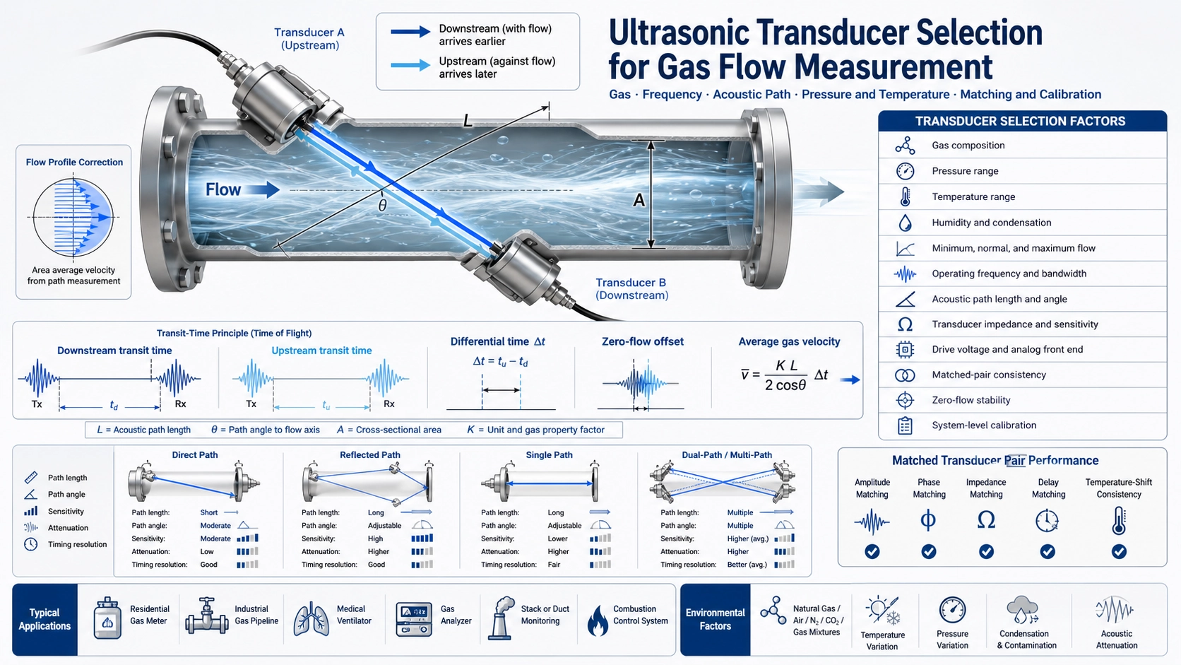
Gas flow transducer selection is a system-design task
Ultrasonic gas flow measurement is used in residential and commercial gas meters, industrial process lines, ventilators, analyzers, combustion systems, and stack or duct monitoring. The transducers are only one part of the system. Their suitability depends on the gas, flow tube, acoustic path, pressure, temperature, frequency, electronics, calibration method, and production consistency.
A transducer that produces a strong signal in room air on a bench may not remain stable in the final meter. Pipe geometry, reflectors, gas composition, pressure, temperature, contamination, cable loading, and the analog front end can change the amplitude, phase, zero-flow offset, and time-of-flight measurement.
How transit-time gas flow measurement works
A typical meter uses two transducers. One measurement is made with the flow and another against it. The acoustic wave travelling downstream arrives slightly sooner, while the upstream wave arrives slightly later. The differential transit time is related to the average gas velocity along the acoustic path. Pipe area, path geometry, calibration, and flow-profile correction are then used to calculate volume or mass flow.
The time difference is usually much smaller than the total transit time. For this reason, waveform stability, transducer matching, timing resolution, and low-noise detection are critical. At zero flow, the ideal differential time is zero, but real transducers and electronics introduce offsets that must be characterized and compensated.
Define the gas and operating envelope first
| Project input | Why it matters |
|---|---|
| Gas composition | Changes sound speed, attenuation, density, and acoustic impedance |
| Pressure range | Affects density, signal strength, mechanical design, and safety rating |
| Temperature range | Changes sound speed, transducer resonance, tube dimensions, and electronics |
| Humidity or condensation | Can attenuate the signal or contaminate transducer and reflector surfaces |
| Minimum and maximum flow | Defines required differential-time resolution and flow-profile range |
| Accuracy and approval | Determines calibration, traceability, diagnostics, and production controls |
Do not select from pipe diameter alone. A domestic natural-gas meter, a medical ventilator, a compressed-air line, and a hot flue-gas duct have very different acoustic and regulatory requirements.
Frequency is a trade-off between coupling, attenuation, size, and timing
Higher frequency can support shorter wavelengths, smaller active elements, and precise timing features, but attenuation in gas generally increases with frequency and path length. Lower frequency often provides more propagation margin over a long path, but it may require a larger transducer and can increase ringing or reduce timing detail.
The optimum frequency depends on the gas, pressure, path length, aperture, required bandwidth, tube dimensions, and electronics. Common project frequencies may be in the hundreds of kilohertz, but a number should never be chosen only because it is common in another meter. Evaluate received amplitude, signal-to-noise ratio, waveform consistency, temperature shift, and zero-flow drift across the full operating envelope.
Acoustic path and tube geometry
The acoustic path may be direct, reflected, single-path, dual-path, or multi-path. A longer diagonal path increases the transit-time difference for a given velocity, which can improve sensitivity, but it also increases attenuation and makes the signal more sensitive to temperature, gas composition, and alignment. Reflectors make compact folded paths possible but add surface condition, angle, and assembly tolerances.
- Direct path: simpler acoustic interpretation, but may require transducers on opposite sides of the tube.
- Reflected path: compact packaging and longer effective path, but reflector geometry and contamination become critical.
- Multiple paths: better representation of a distorted velocity profile, but more channels, cost, calibration, and processing.
Path angle, bore diameter, upstream disturbances, valves, bends, screens, and flow conditioners affect the relationship between path velocity and average pipe velocity. Final accuracy requires calibrated system behavior, not only an accurate time measurement.
Pressure and temperature influence both acoustics and mechanics
Higher gas pressure often increases density and can improve acoustic coupling, but the transducer, seal, housing, feedthrough, and flow tube must be rated for the pressure and gas. Pressure also changes mechanical loading and can shift resonant behavior.
Temperature changes the speed of sound, transducer impedance, resonance, matching network, tube dimensions, reflector spacing, and analog electronics. A robust design measures temperature at a representative location and validates the entire system at temperature extremes. A compensation formula cannot correct a waveform that has become too weak, distorted, or misdetected.
Gas composition and sound speed
Natural gas composition can vary, and industrial gas applications may involve air, oxygen, nitrogen, carbon dioxide, hydrogen blends, refrigerants, anesthetic gases, or process mixtures. Composition affects sound speed and attenuation. If the meter assumes a fixed gas property while the mixture changes, both flow conversion and signal timing windows may be affected.
Determine whether the project reports actual volume, standard volume, mass flow, or another quantity. Pressure and temperature compensation may be required, and some applications need gas-composition input or calibration for defined mixtures.
Transducer construction and acoustic interface
Gas-coupled transducers require efficient transfer of energy into a low-density medium. The radiating membrane, matching layer, backing, housing cavity, port, protective mesh, and mounting stress all influence output and bandwidth. A protective structure that is mechanically robust may also reduce signal or create an additional resonance.
Confirm chemical compatibility, leak tightness, pressure rating, ingress protection, flame or hazardous-area requirements, and whether the transducer contacts the process gas directly. For medical and breathing applications, material and cleanliness requirements are especially important.
Matched pairs and production consistency
Two transducers in a transit-time path should be evaluated as a pair. Differences in amplitude, phase, impedance, temperature shift, and delay can create zero-flow offset and temperature-dependent drift. Pair matching can improve performance, but the production strategy must define what is measured, the matching tolerance, and whether pairs must remain together through assembly and service.
Lot-to-lot consistency is often more important than a single high-sensitivity sample. Evaluate multiple parts from different production lots, then define acceptance limits for impedance, frequency, amplitude, phase, and temperature shift that correlate with meter performance.
Electronics, timing, and signal processing
The driver must produce sufficient acoustic energy without overstressing the transducer. The receiver must detect a repeatable timing feature while rejecting electrical crosstalk, switching transients, flow noise, and acoustic multipath. Useful design parameters include burst cycles, drive voltage, gain, filter bandwidth, threshold or correlation method, sampling rate, timing window, and averaging.
At low flow, the differential time can approach the system’s offset and noise floor. At high flow, the waveform shifts in time and can change shape. The capture window must cover temperature and flow variation. Diagnostics should detect weak signal, missing path, excessive gain, abnormal zero drift, transducer disconnection, and contamination where possible.
Calibration is required at system level
Transducer characterization cannot replace meter calibration. The relationship between differential time and flow depends on the actual tube, path, reflectors, flow profile, Reynolds number, gas properties, and assembly tolerances. Calibrate with a traceable reference across representative flow, pressure, temperature, and gas conditions required by the project.
Use zero-flow tests to establish offset, repeated flow points to assess repeatability, and temperature cycling to assess drift. For regulated metering, follow the applicable approval and verification requirements rather than using a laboratory development curve as the final product specification.
A practical selection and RFQ checklist
- Application: gas meter, ventilator, analyzer, duct, process line, or other equipment
- Gas or gas mixtures, humidity, contamination, and condensation risk
- Pipe or tube diameter, material, geometry, and available mounting space
- Direct, reflected, single-path, or multi-path architecture
- Acoustic path length and angle
- Minimum, normal, and maximum flow
- Pressure and temperature range
- Required frequency, bandwidth, impedance, and sensitivity targets
- Drive voltage, burst cycles, repetition rate, and analog front end
- Accuracy, zero stability, calibration, approval, and lifetime requirements
- Housing, seal, cable, connector, and process compatibility
- Prototype quantity, validation plan, and expected production volume
Our broader ultrasonic sensor selection guide explains how medium and application change the transducer requirements. For custom development, use the custom transducer RFQ guide.
Texas Instruments provides detailed primary references on ultrasonic transducer selection for gas metering and the gas meter design process. These references also emphasize production consistency, tube design, iterative testing, and calibrated flow validation.
FAQ
Is a higher-frequency gas transducer always more accurate?
No. Higher frequency may improve timing detail and reduce size, but it can also increase attenuation and reduce propagation margin. Accuracy depends on the complete path, electronics, calibration, and operating conditions.
Can one transducer model work for air and natural gas?
Possibly, but it must be validated. Sound speed, attenuation, pressure, safety, material compatibility, timing windows, and calibration differ between gases and applications.
Why are matched pairs important?
Amplitude, phase, delay, impedance, and temperature shift differences can create zero-flow offset and drift. Pair matching reduces one source of asymmetry, although system calibration is still required.