Commissioning begins with the hydraulic structure, not the controller menu
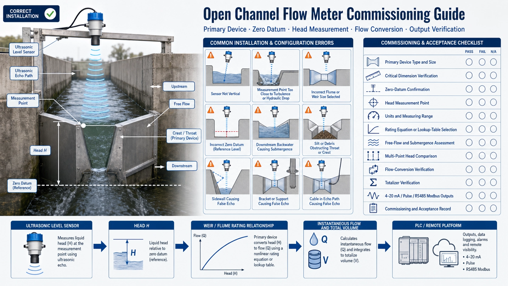
An open channel flow meter does not measure flow independently. It measures liquid head at a defined location and converts that head through the rating relationship of a weir, flume, or other primary measuring device. A correct ultrasonic distance reading can therefore produce an incorrect flow value if the wrong structure, size, zero datum, measurement point, or equation has been entered.
This article focuses on field commissioning after the measuring structure has been selected and installed. For the operating principle and common weir and flume types, see our open channel flow meter guide.
Verify the primary device before configuring the instrument
Identify the exact structure and confirm its critical dimensions. “Parshall flume,” “V-notch,” or “rectangular weir” is not enough. Parshall flumes of different throat widths are not geometrically proportional, and modified or damaged structures may not follow the original calibration. Record the manufacturer, model, throat width or notch geometry, channel dimensions, serial number where available, and the reference drawing.
| Item to verify | Why it matters |
|---|---|
| Structure type and size | Selects the correct level-to-flow relationship |
| Critical dimensions | Confirms that the installed structure matches the selected table or equation |
| Upstream approach | Distorted, swirling, or rapidly varying flow changes the measured head |
| Downstream condition | Backwater or submergence can invalidate a free-flow equation |
| Deposits and damage | Silt, debris, corrosion, or deformation changes the effective geometry |
Inspect the structure under safe conditions. Remove debris that obstructs the throat or crest, check for leakage around the structure, and verify that the channel is level and aligned as required. Software cannot correct a structure whose geometry or hydraulic condition is wrong.
Establish the zero datum
The zero datum is the hydraulic reference from which head is measured. It is not automatically the channel bottom, sensor mounting plate, or lowest water surface visible during commissioning. For a weir it is generally related to the crest elevation; for a flume it is defined by the calibrated measurement section.
- Identify the official zero or crest reference on the drawing.
- Measure the vertical relationship between that reference and the ultrasonic sensor face.
- Enter the empty distance or zero offset according to the controller’s parameter logic.
- Record the datum with a permanent survey mark or dimension so it can be re-established after sensor replacement.
A few millimetres of level error can produce a much larger percentage flow error at low head because the rating relationship is nonlinear. Do not hide an uncertain datum with an arbitrary flow correction factor.
Confirm the head measurement point
Each structure defines where upstream head must be measured. The ultrasonic sensor should observe a representative surface at that location, not a local wave created by the throat, a drop, an inlet jet, or a wall reflection. Verify the longitudinal distance from the crest or throat, the lateral position, sensor verticality, blind-zone clearance, and acoustic path.
- Avoid mounting directly above aerated, falling, or highly turbulent water.
- Keep the beam away from sidewalls, brackets, cables, and the edge of the flume.
- Use damping to stabilize normal surface ripple, but do not use heavy damping to conceal hydraulic instability.
- Where foam is intermittent, compare the raw distance and echo strength during both clear and foamy conditions.
Enter the structure parameters and units
Select the exact built-in flume or weir program where available. Confirm the dimension units before entering throat width, notch angle, crest length, exponent, coefficient, or lookup-table data. If a custom equation is used, document its source, applicable head range, and whether it assumes free flow.
Do not mix millimetres with metres, litres per second with cubic metres per hour, or instantaneous-flow units with totalizer units. Confirm the decimal position on local display, analog output, pulse output, Modbus registers, and the remote platform.
Check free-flow and submerged conditions
Many standard rating equations assume free flow. Downstream water that rises high enough can submerge the structure and change the head-discharge relationship. A single upstream ultrasonic sensor cannot always correct this condition. Some systems require a second downstream level measurement and a structure-specific submergence correction; others should declare the result invalid above a defined submergence ratio.
During commissioning, record downstream water level at representative flows and check whether the installation stays within the structure’s valid operating condition. Also inspect for bypass flow around the structure, leakage through a closed gate, and upstream ponding that changes the approach velocity.
Verify level before verifying flow
Compare the instrument head with an independent level reference such as a staff gauge, point gauge, surveyed ruler, or another suitable method. Take readings after the surface has stabilized and use the same datum. Verify at several heads if the process permits.
| Observed result | Likely area to check |
|---|---|
| Constant head offset | Sensor reference, zero datum, mounting height, units |
| Error grows with level | Span, geometry, wrong structure size, distance-to-level conversion |
| Head correct but flow wrong | Equation, coefficient, exponent, units, submergence condition |
| Local flow correct but PLC wrong | 4–20mA scaling, pulse weight, register, decimal factor |
Verify flow conversion and totalization
Once head is confirmed, compare the controller’s calculated flow with the official table or equation for the installed structure. Use at least two or three head values across the practical range where possible. A single-point flow adjustment can make one value agree while leaving the rest of the curve wrong.
Check the totalizer separately. Confirm the integration time, total unit, pulse weight, rollover behavior, reset protection, and whether reverse or invalid-flow conditions are counted. Run a timed test at reasonably stable flow and confirm that the increase in total volume is consistent with the average instantaneous flow.
Check outputs and remote data
- For 4–20mA, confirm whether 4 mA represents zero flow and what flow corresponds to 20 mA.
- For pulse output, confirm volume per pulse, pulse width, polarity, and maximum frequency.
- For RS485/Modbus, verify address, baud rate, parity, register, unit, signed format, and decimal scaling.
- For telemetry, compare timestamps and totals to identify delayed or cached values.
- Test relay alarms using controlled thresholds without disturbing the hydraulic zero.
Create a commissioning and acceptance record
The final record should include site, channel, structure type and size, measured dimensions, datum sketch, sensor model and serial number, mounting height, blind zone, head range, equation or table source, units, damping, submergence assessment, level comparisons, flow comparisons, totalizer test, output settings, photographs, and acceptance result. This baseline is essential when later troubleshooting drift, deposits, sensor replacement, or changes to the channel.
The U.S. Bureau of Reclamation Water Measurement Manual provides detailed engineering references for weirs, flumes, measurement locations, and submerged-flow conditions. Project requirements and local regulations remain controlling.
FAQ
Can I calibrate the flow meter by changing only one coefficient?
Only when the hydraulic structure and equation are already confirmed and the project procedure permits it. A coefficient should not be used to conceal an incorrect zero, wrong flume size, poor measurement point, or submerged condition.
Why is low-flow error often large?
At low head, a small level error can represent a large percentage of the calculated flow. Datum accuracy, deposits, surface stability, and sensor resolution therefore become especially important.
Does an ultrasonic sensor need to touch the water?
No. It normally measures the upstream surface without contact, but the acoustic path, mounting distance, foam, condensation, and surface turbulence must still be controlled.